Audio laser transmission
Introduction
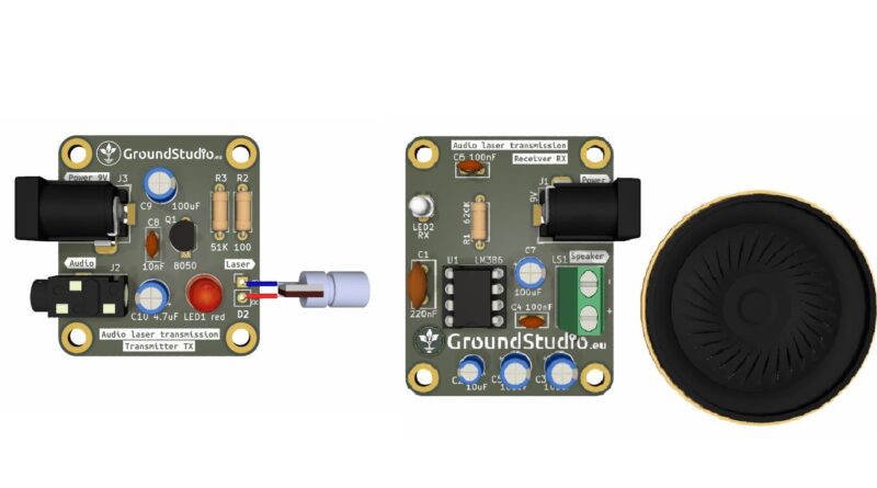
With this kit we can transmit audio signals wirelessly from one board to another, only through the light emitted by a laser diode.
List of tools required for assembly and operation,
not included in the kit
| Name | Image | Buy here |
|---|---|---|
| Soldering iron | 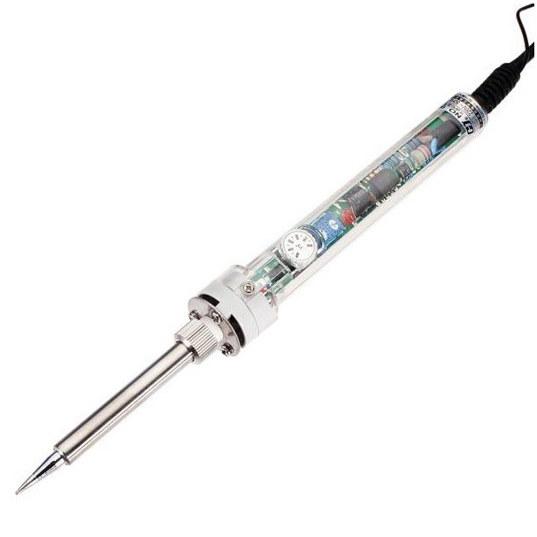 | |
| Solder wire |  | |
| Pliers |  | |
| Helping hands (device or a friend) | 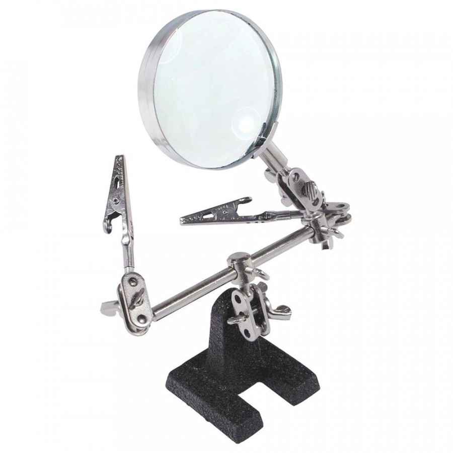 | |
| Audio source* | ||
9V Power supply** |
* As an audio source, we recommend an inexpensive device, such as this Bluetooth receiver, to be connected to the kit. If the kit is not properly assembled, the audio device can become damaged. Do not use a smartphone wire connected to the kit,
| Bluetooth reveiver + Jack 3.5 cable | 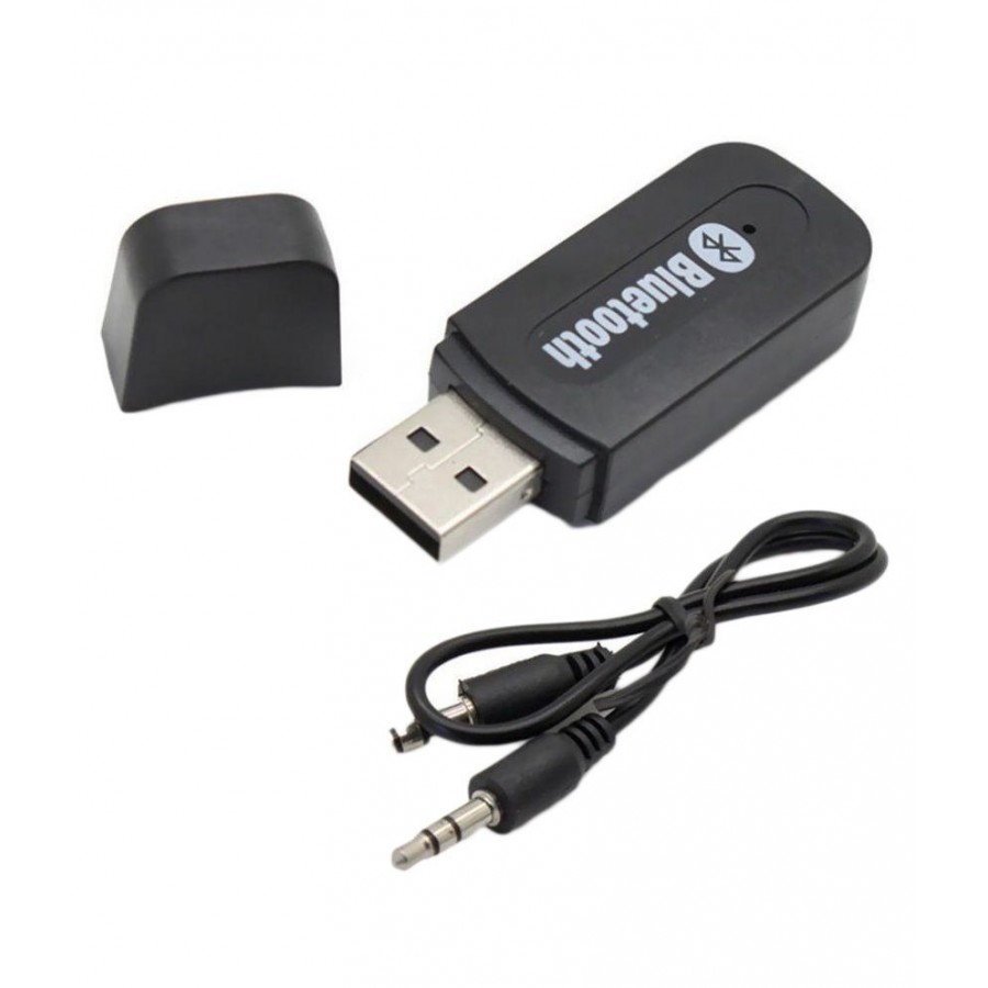 | |
| 5V USB power supply | 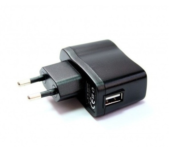 |
**To power the circuit, you’ll need a 9V power supply with a DC connector.
Here are some suggestions:
| Connector for 9V battery + battery | 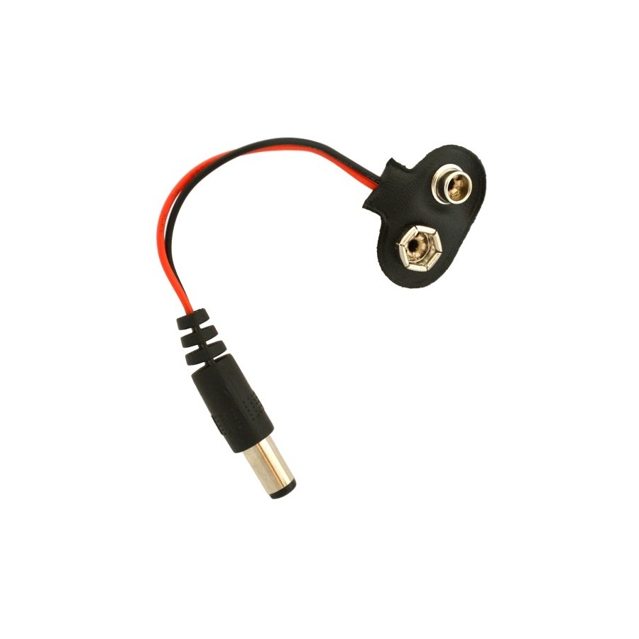 + 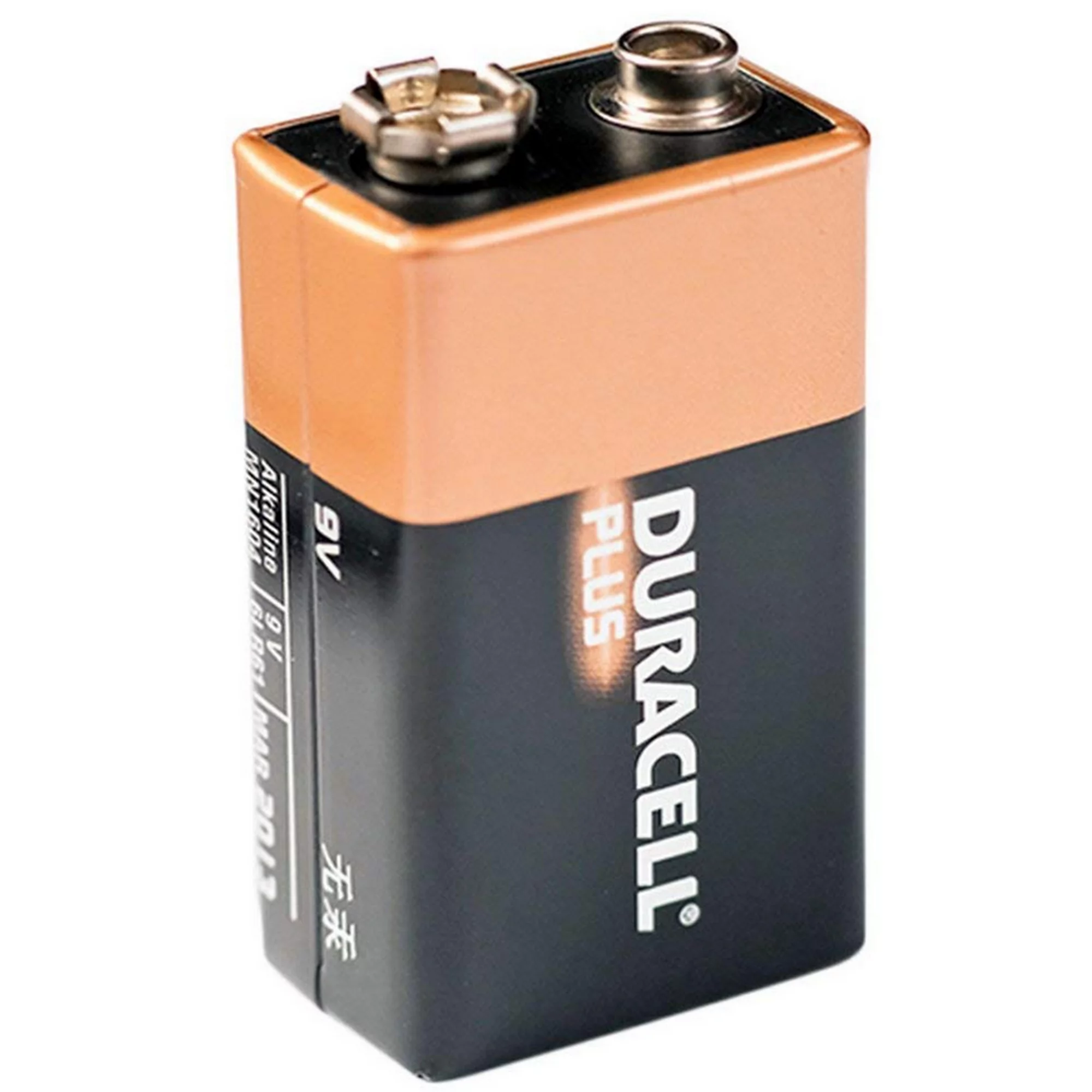 | |
| 9V power supply | 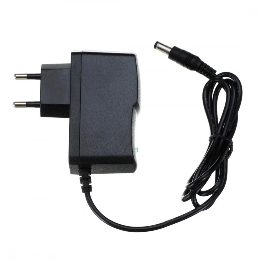 |
List of components included in the kit
| Qty | Name | Details | Footprint | Image |
|---|---|---|---|---|
| 1 | Resistor | 620K | R1 | 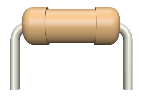 |
| 1 | Resistor | 100R | R2 |  |
| 1 | Resistor | 51K | R3 |  |
| 1 | Laser Diode | red | D2 | 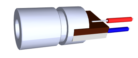 |
| 1 | Photodiode | D1 | ||
| 1 | Electrolytic capacitor | 10uF | C2 | 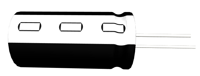 |
| 4 | Electrolytic capacitor | 100uF | C3, C5, C7, C9 |  |
| 1 | Electrolytic capacitor | 4.7uF | C10 |  |
| 1 | Ceramic capacitor | 220nF | C1 | 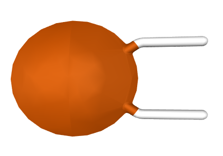 |
| 2 | Ceramic capacitor | 100nF | C4, C6 |  |
| 1 | Ceramic capacitor | 10nF | C8 |  |
| 2 | Transistor | 8050 | Q1 | 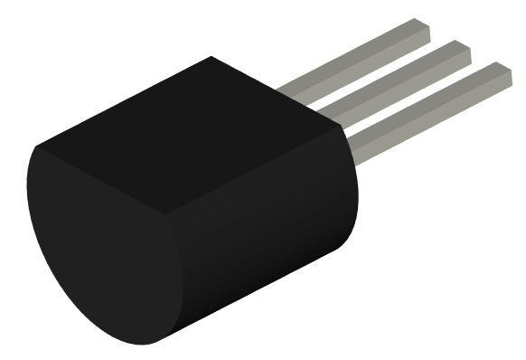 |
| 12 | LED | red, 5mm | LED1 | 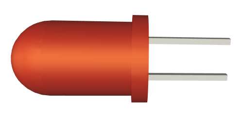 |
| 1 | Integrated circuit | LM386 | U1 | 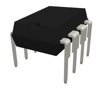 |
| 1 | Socket | 8 pins | U1 | 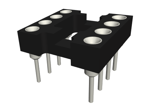 |
| 2 | Power connector | jack barrel, 9V | J1, J3 | 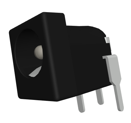 |
| 1 | Audio connector | jack 3.5 | J2 | 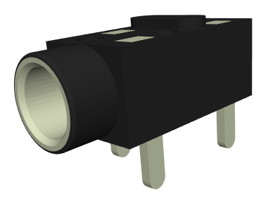 |
| 1 | Speaker | 8ohm | 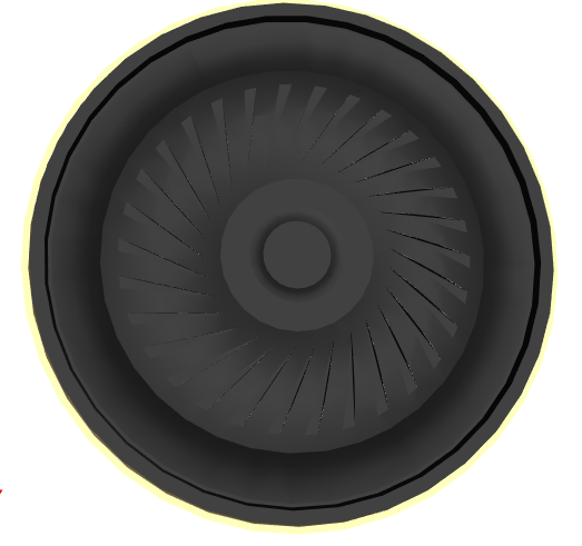 | |
| 1 | Cable for speaker | |||
| 1 | PCB | 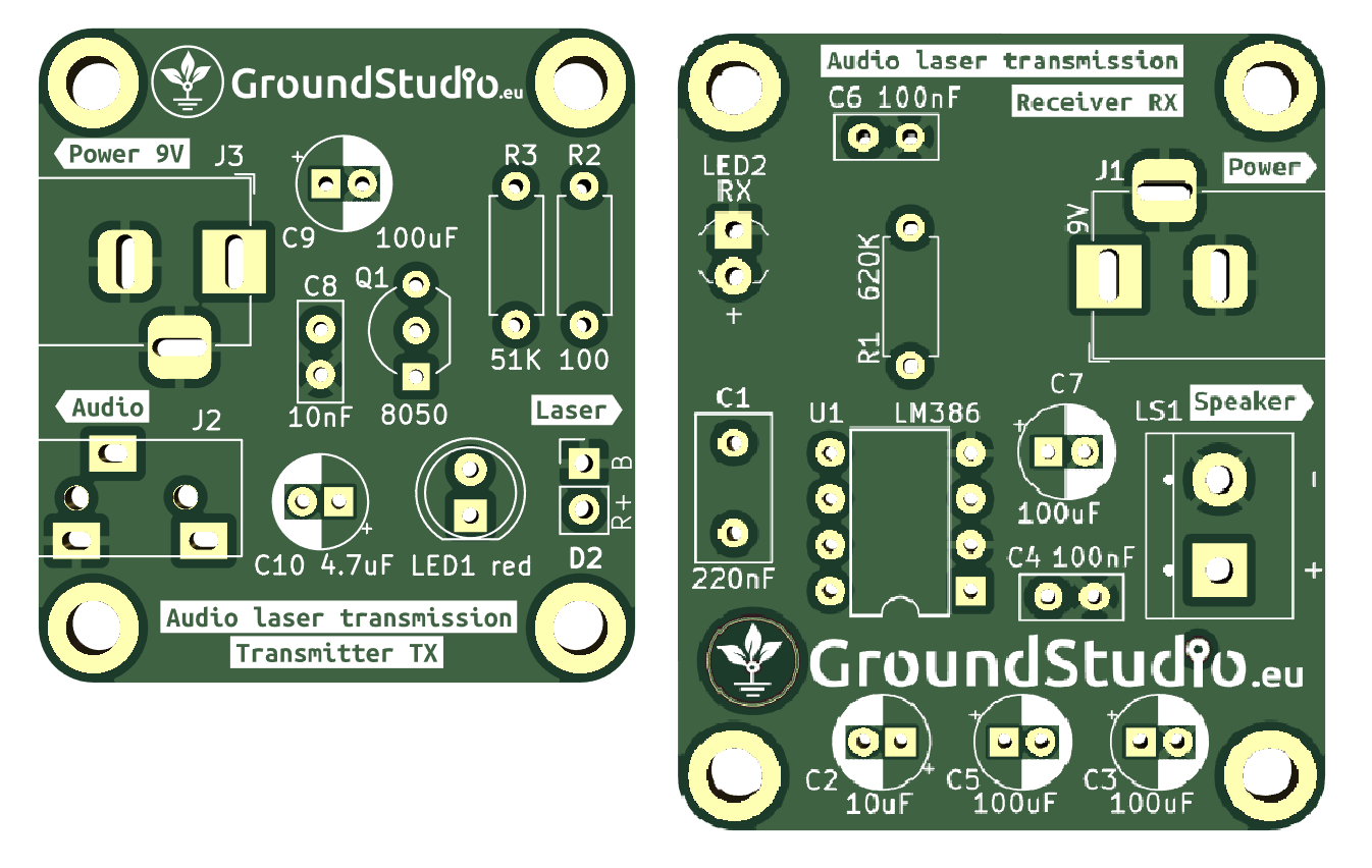 |
Schematic
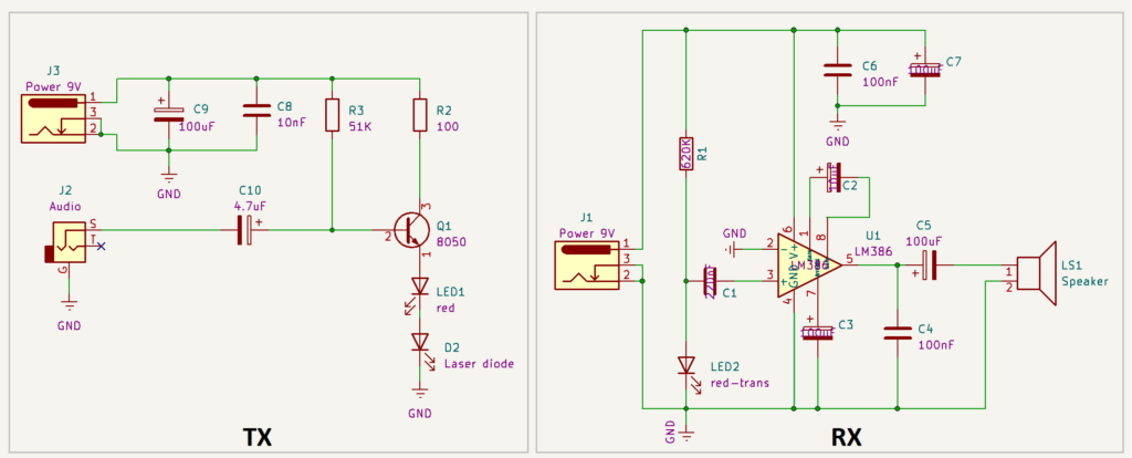
Operating principle
The circuit consists of two parts: the transmitter and the receiver. The audio signal source is connected to the transmitter, and the receiver plays the audio signal through a speaker.
Transmitter (TX)
As input element in the transmitter we have the audio signal (through the J2 jack connector) and a 9V voltage source (the J3 connector). The output is the light generated by the laser diode D2. The audio signal is generally a weak signal with an alternating form (both negative and positive). The role of the NPN bipolar transistor 8050 is to shift the audio signal to a positive voltage so that it can light up the laser diode. Without this offset, the laser diode would not illuminate and would not be able to transmit the signal to the other board.
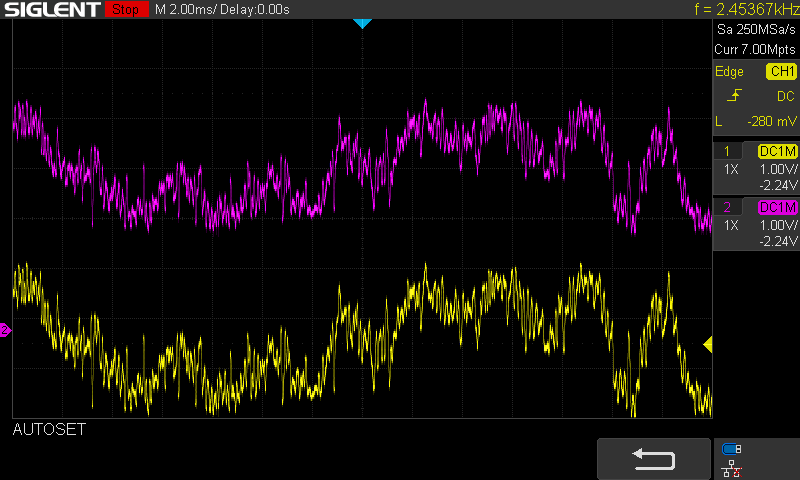
In the screenshot below, two probes are connected to the oscilloscope:
- Yellow for the input audio signal
- Purple for the signal on the laser diode It can be observed that the yellow signal is centered around the value of 0V, while the purple signal is shifted by approximately 3V. These 3V represent the voltage needed for the laser diode to illuminate, with varying light intensity, depending on the voltage value in the signal.
Receiver (RX)
The key components in the receiver are the photodiode, the LM386 audio amplifier, and the speaker. The light signal transmitted by the laser diode is received by the photodiode. When light is applied to the photodiode, it generates electricity (photovoltaic effect). The LM386 amplifier amplifies the voltage generated by the LED, with a significantly higher power supply voltage (9V on pin 1-GAIN) than the voltage generated by the photodiode(in millivolts). The amplified signal is then played through the speaker, making it audible.
Instructions for assembly preparation
| Step 0 | Read all the instructions, from beginning to end. |
| Step 0 bis | Reminder: It is very important to read all the instructions. |
| Step 1 | Make sure you have all the tools needed to assemble the kit. |
| Step 2 | Make sure you have all the components needed to assemble the kit. |
| Step 3 | To comply with the warranty conditions*, check/measure each component separately. |
Assembly instructions
| Step | Details | Image |
|---|---|---|
| Step 1 | Solder the resistors according to the markings on the PCB, regardless of orientation. Make sure you respect the values and markings | |
| Step 2 | Solder the ceramic capacitors, regardless of orientation | |
| Step 3 | Solder the electrolytic capacitors, so that the shorter terminal (the negative one, the cathode) corresponds to the hatched area on the PCB | |
| Step 4 | Solder the transistor, so that the cut-out marking correspond to the one on the PCB | |
| Step 5 | Solder the LED and the photodiode so that the longer terminal (the positive one) corresponds to the “+” sign on the PCB | |
| Step 6 | Solder the socket, so that the cut-out marking correspond to the one on the PCB | |
| Step 7 | Solder the power connector according to the marking on the PCB | 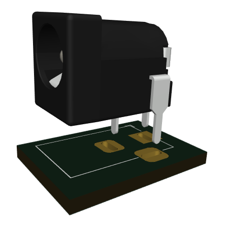 |
| Step 8 | Solder the audio connector according to the marking on the PCB | 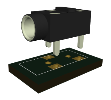 |
| Step 9 | Insert the integrated circuit in its socket, so that the cut-out marking correspond to the one on the PCB | |
| Step 10 | Solder the laser diode to the marked pads, blue wire goes to B and red wire goes to R+ | 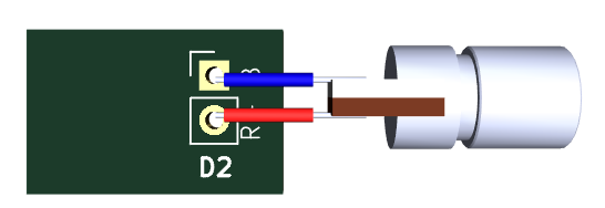 |
| Step 11 | Power the circuit with the chosen power supply | 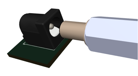 |
| Step 12 | Link the bluetooth receiver to your smartphone, play your favourite music, and connect the audio cable to the kit | 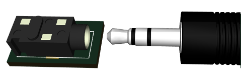 |
| Step 13 | Direct the laser diode towards the photodiode | 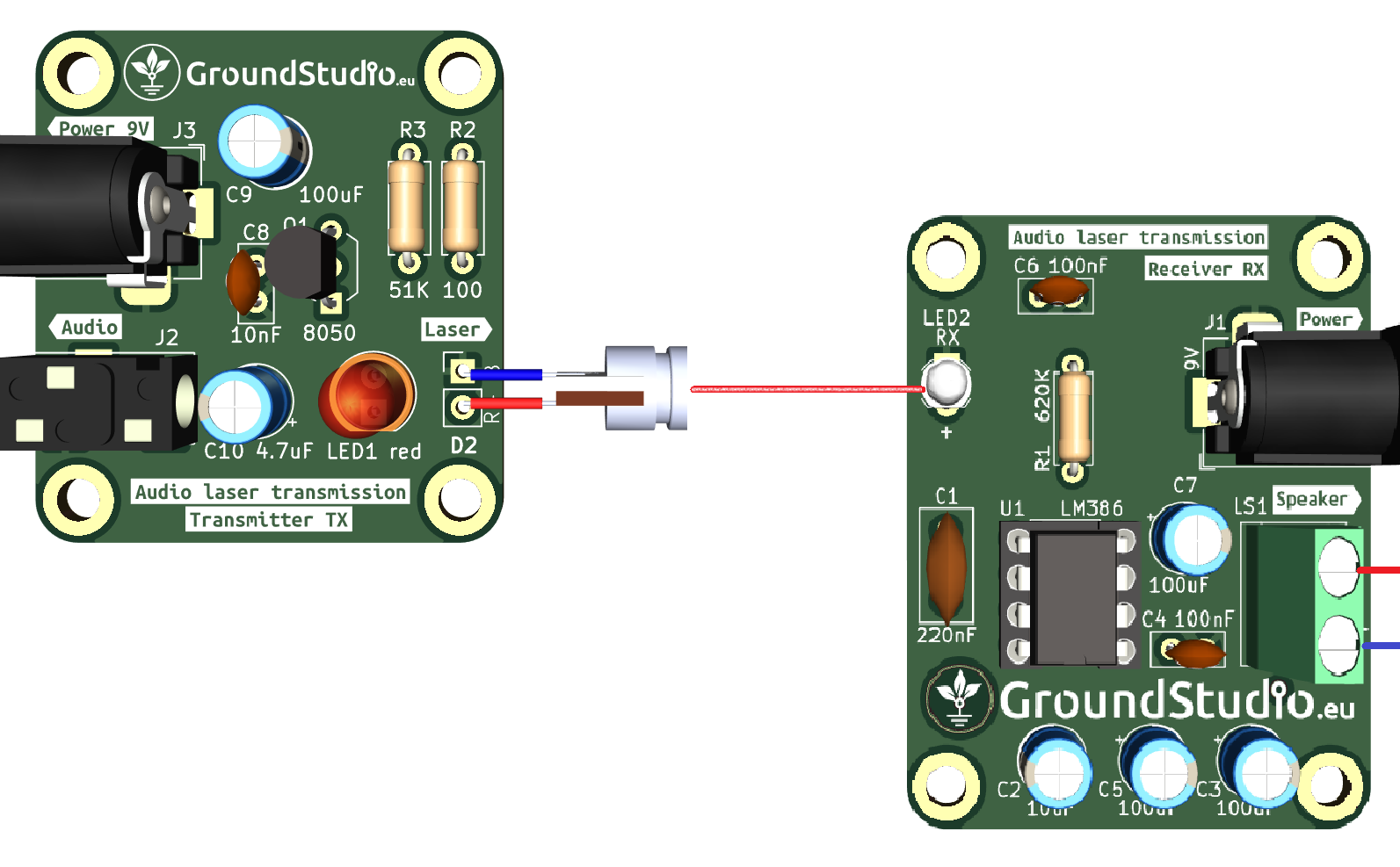 |
| Step 14 | And enjoy your laser transmitted music! |  |
General assembly instructions for Warranty Compliance
As a precaution and to comply with the warranty conditions, we recommend testing each individual component before assembly. For example, resistors will be measured with an ohmmeter/multimeter. The warranty is for each individual component, not for the whole assembly. Since assembly is done by unauthorized personnel, under unknown conditions or at unknown stages of completion, we cannot assume any legal liability related to any consequences or operation of devices assembled by any third party.

