Blinky Christmas Tree DIY
Introduction
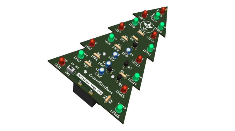
This circuit simulates the blinking light of a Christmas Tree. It consists of 16 LEDs, 8 red and 8 green, divided into 4 zones that blink at different frequencies. Unlike other blinking light generator circuits that use integrated circuits, the circuit in this kit uses only transistors as active elements. It can be powered by a 9V battery and used as a standalone device.
List of tools required for assembly and operation,
not included in the kit
| Name | Image | Buy here |
|---|---|---|
| Soldering iron |  | |
| Solder wire |  | |
| Pliers |  | |
| Phillips screwdriver |  | |
| 9V battery |  |
List of components included in the kit
| Qty | Name | Details | Footprint | Image |
|---|---|---|---|---|
| 4 | Resistor | 1K | R1 – R4 |  |
| 2 | Resistor | 75K | R5, R6 |  |
| 2 | Resistor | 100K | R7, R8 |  |
| 8 | LED | 5mm, red | LED1, LED3, LED5, LED7, LED9, LED11, LED13, LED15 |  |
| 8 | LED | 5mm, green | LED2, LED4, LED5, LED8, LED10, LED12, LED14, LED16 |  |
| 4 | Transistor | 8050, bipolar NPN | Q1 – Q4 | 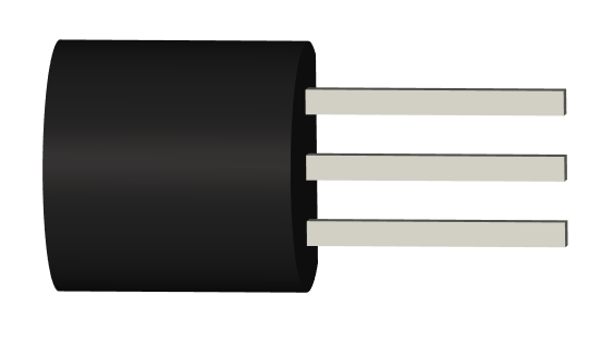 |
| 4 | Electrolytic capacitor | 10uF | C1 – C4 |  |
| 1 | Slider button | SW1 | 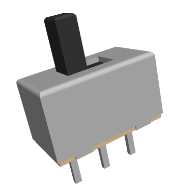 | |
| 1 | Battery holder | 9V | J1 |  |
| 1 | PCB | 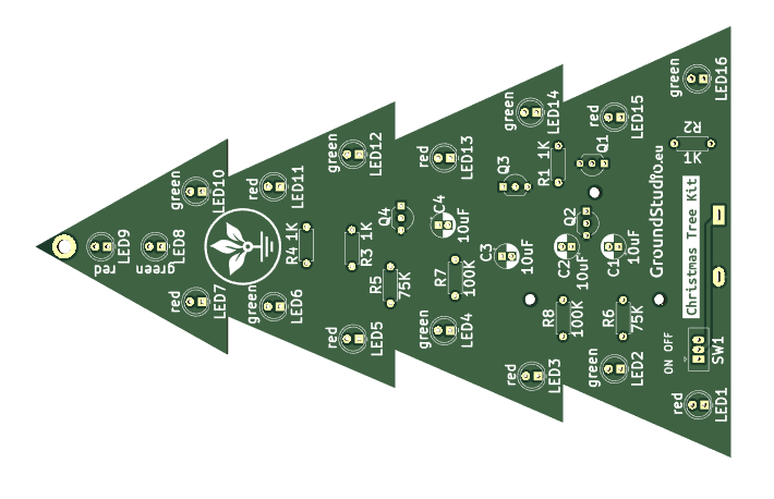 |
Schematic
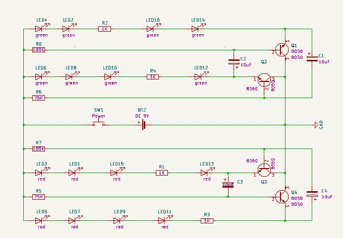
Working principle
The circuit is composed of two bistable multivibrators (flip-flop):
- The first one is formed by transistors Q1 and Q2, along with capacitors C1 and C2, and intermittently controls the branches of LEDs LED4-LED14 and LED6-LED12.
- The second one is formed by transistors Q3 and Q4, along with capacitors C3 and C4, and intermittently controls the branches of LEDs LED4-LED14 and LED6-LED12.
Each bistable, as the name suggests, has two states. In our case, these states are intermittent. With two bistables, each having two states, we have a total of 4 states that form the light game.
Observing the blinking light, we can see that the 4 states have different frequencies. The frequency of a state change depends on the voltage between the base and emitter of the tranzsitors. Both bistables are powered at the same voltage, have capacitors and resistors of the same values, and the same number of LEDs… what makes the base-emitter voltage of the two bistables differ? Well, it’s the color of the LEDs. Green LEDs have a higher voltage drop than red LEDs. Thus, we have an imbalance, a difference in voltage between the two bistables, resulting in different blink frequencies.”
Instructions for assembly preparation
| Step 0 | Read all the instructions, from beginning to end. |
| Step 0 bis | Reminder: It is very important to read all the instructions. |
| Step 1 | Make sure you have all the tools needed to assemble the kit. |
| Step 2 | Make sure you have all the components needed to assemble the kit. |
| Step 3 | To comply with the warranty conditions*, check/measure each component separately. |
Assembly instructions
| Step | Details | Image |
|---|---|---|
| Step 1 | Solder the resistors according to the markings on the PCB, regardless of orientation. Make sure you respect the values and markings | |
| Step 2 | Solder the LEDs so that the longer terminal (the positive one) corresponds to the “+” sign on the PCB | |
| Step 3 | Solder the electrolytic capacitors, so that the shorter terminal (the negative one, the cathode) corresponds to the hatched area on the PCB | |
| Step 4 | Solder the transistor according to the marking on the PCB | |
| Step 5 | Solder the SW1 push button according to the marking on the PCB, regardless of orientation | 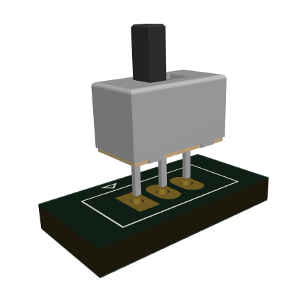 |
| Step 6 | Screw the battery holder | 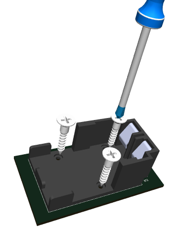 |
| Step 7 | Solder the battery holder | 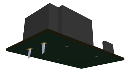 |
| Step 8 | Plug the 9V battery and put the slider button on the ON position |  |
| Step 9 | Enjoy your Blinky Christmas Tree! |  |
General assembly instructions for Warranty Compliance
As a precaution and to comply with the warranty conditions, we recommend testing each individual component before assembly. For example, resistors will be measured with an ohmmeter/multimeter. The warranty is for each individual component, not for the whole assembly. Since assembly is done by unauthorized personnel, under unknown conditions or at unknown stages of completion, we cannot assume any legal liability related to any consequences or operation of devices assembled by any third party.

