Kit de învățare cu 555 și 4017
Introducere
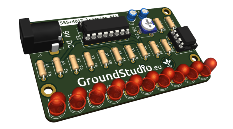
Acest circuit generează un joc de luminiă de tip "Knight Rider" prin aprinderea secvențială a fiecărui LED, de la stânga la dreapta. Este un circuit ideal pentru a înțelege principiul de funcționare al timerului 555 împreună cu numărătorul zecimal 4017.
Lista cu uneltele necesare asamblării și funcționării
neincluse in kit
| Nume | Imagine | Cumpără |
|---|---|---|
| Letcon | 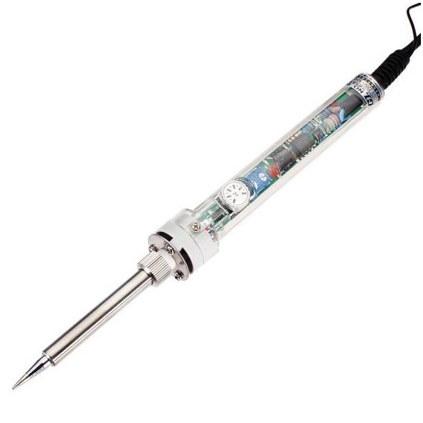 | |
| Fludor | 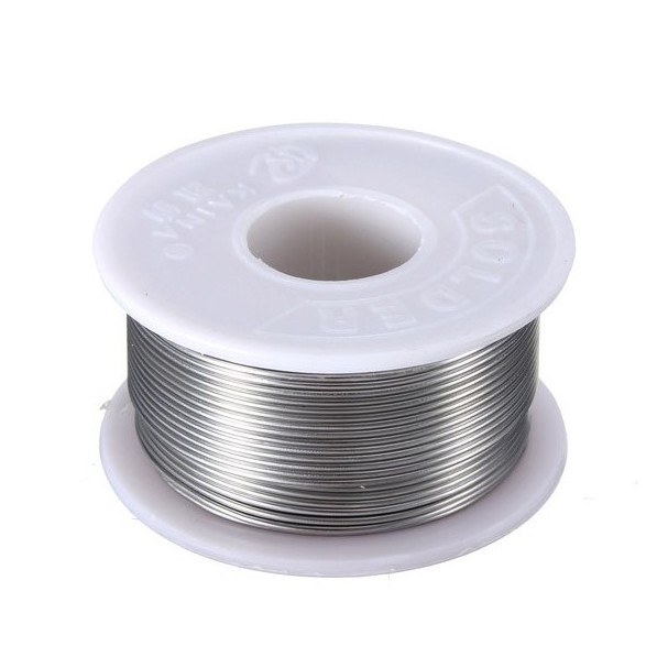 | |
| Clește pentru fire | 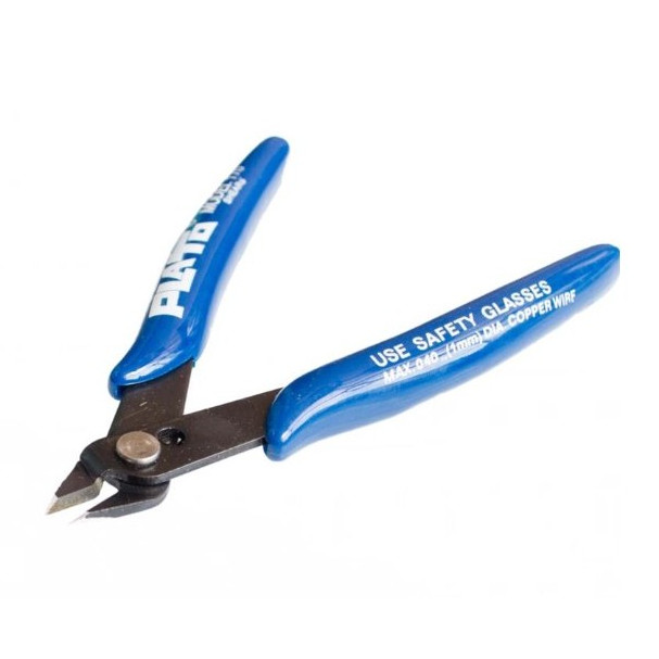 | |
| Helping hands (dispozitivul sau un prieten) | 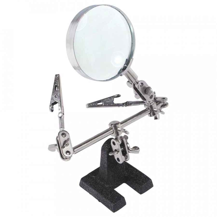 | |
| Șurubelniță Phillips (în cruce) | 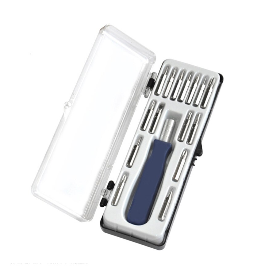 | |
| Sursă de alimentare de 9V |
*To power the circuit, you‘ll need a 9V power supply with a DC connector.
Iată câteva sugestii:
| Nume | Imagine | Buy Here |
|---|---|---|
| Conector pentru baterie de 9V + baterie | 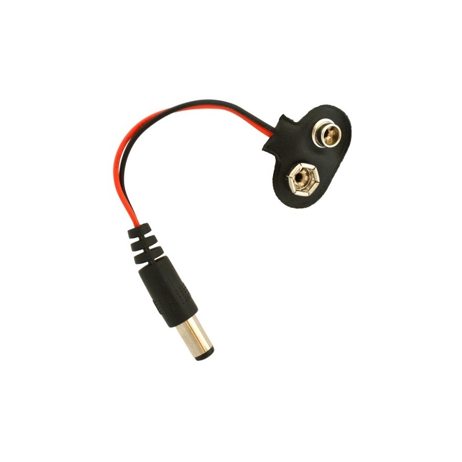 + 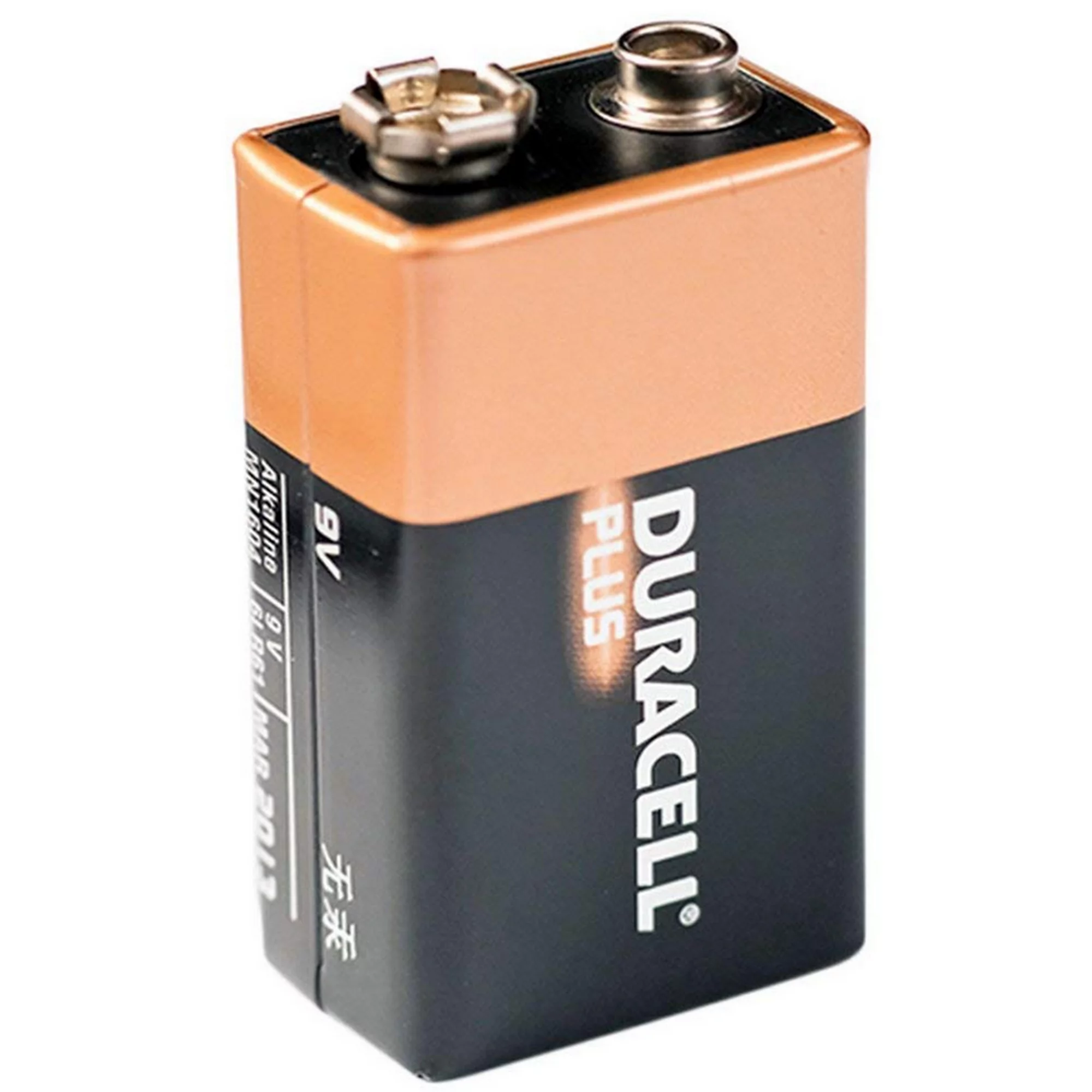 | |
| Alimentator de 9V | 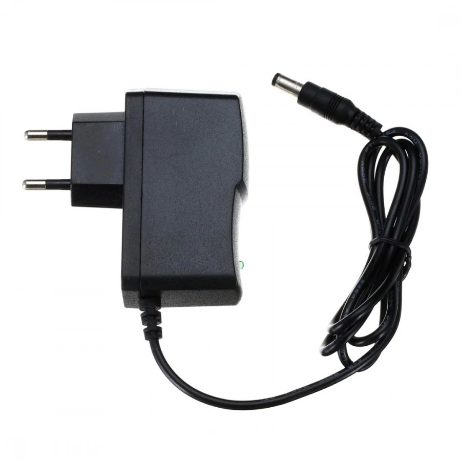 |
Listă cu componentele incluse în kit
| Qty | Nume | Detalii | Footprint | Imagine | Cumpără |
|---|---|---|---|---|---|
| 10 | Rezistor | 1K, 1/4W | R1 – R10 | 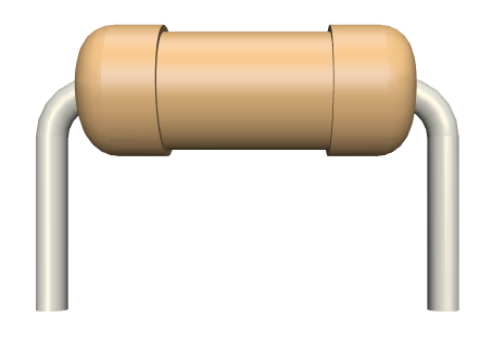 | |
| 1 | Rezistor | 10K, 1/4W | R12 | | |
| 1 | Rezistor | 2.2K, 1/4W | R11 | | |
| 10 | LED | 5mm, roșu | LED1 – LED10 | 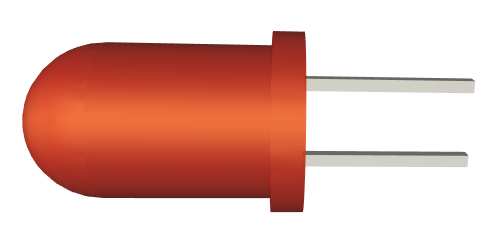 | |
| 2 | Condensator electrolitic | 1uF | C1, C2 | 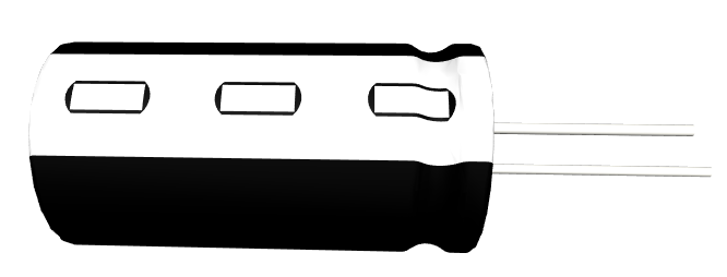 | |
| 1 | Trimmer | 50K (503) | R13 | 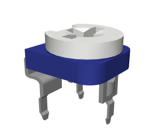 | |
| 1 | Conector pentru alimentare | jack barrel, 9V | J1 | 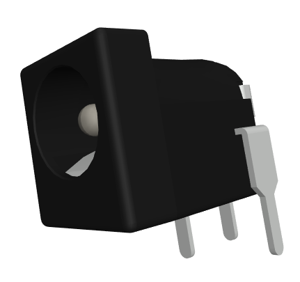 | |
| 1 | Circuit integrat | NE555 | U1 | 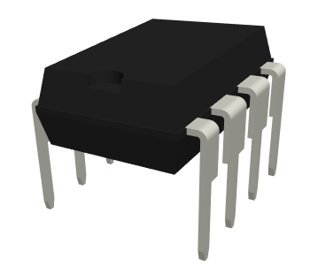 | |
| 1 | Circuit integrat | CD4017 | U2 | 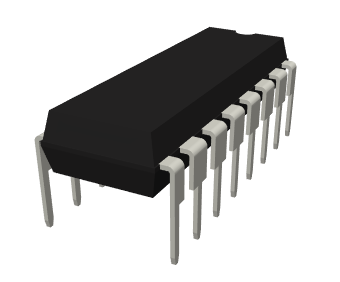 | |
| 1 | Soclu | 8 pins | U1 | 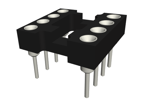 | |
| 1 | Soclu | 16 pins | U2 | 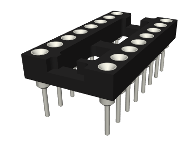 | |
| 1 | PCB | 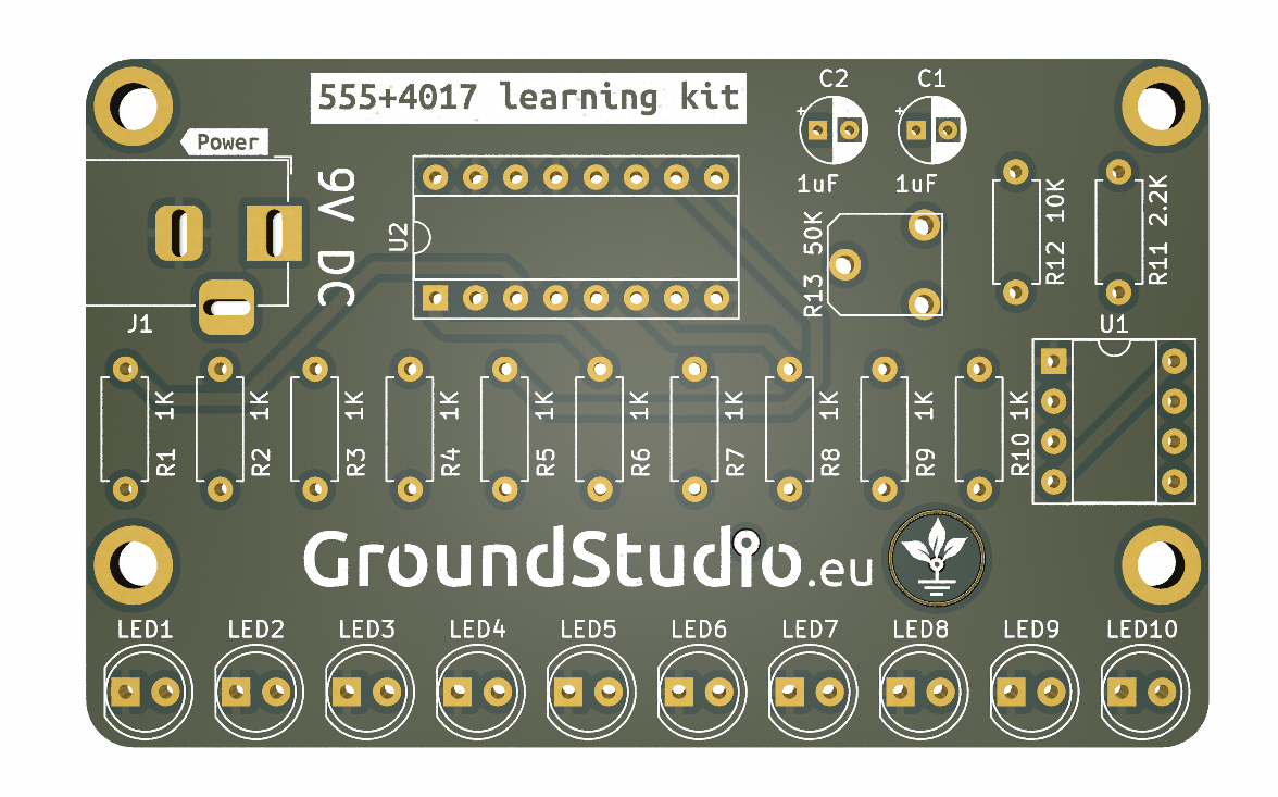 |
Schema electronică
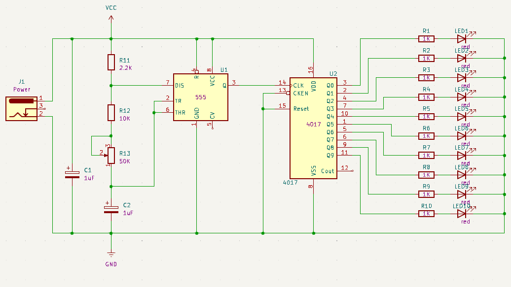
Principiul de funcționare
Acest circuit generează un joc de luminiă de tip "Knight Rider" prin aprinderea secvențială a fiecărui LED, de la stânga la dreapta. Este un circuit ideal pentru a înțelege principiul de funcționare al timerului 555 împreună cu numărătorul zecimal 4017.
Timerul 555 este utilizat ca oscilator, împreună cu R12, R13 și C2. Acest circuit generează un impuls continuu pe pinul Q al circuitului integrat 555.
CD4017 acționează ca un contor zecimal/distribuitor de impulsuri. Mai exact, cu fiecare impuls primit de la timer la intrarea CLK, setează secvențial una dintre ieșirile Q, de la Q0 la Q9, la nivel înalt (HIGH), păstrând toate celelalte la nivel scăzut (LOW). În acest circuit, fiecare ieșire Q corespunde unui LED. Al 11-lea impuls de la timer face ca contorul să reia ciclul de la Q0, iar modelul de lumină continuă. Circuitul va continua să clipească atâta timp cât este alimentat.
Observă rezistorul variabil RV1. Schimbarea rezistenței acestuia va modifica frecvența impulsurilor generate de 555, făcând LED-urile să blinkuie mai rapid sau mai lent. Cu alte cuvinte, RV1 controlează viteza la care LED-urile blinkuie.
Instrucțiuni pentru pregătirea asamblării
| Step | Detalii |
|---|---|
| Pasul 0 | Citește toate instrucțiunile, de la început și până la sfârșit. |
| Pasul 1 bis | Reminder: E foarte important să citești toate instrucțiunile din acest document |
| Pasul 1 | Asigură-te că ai toate uneltele necesare asamblării kitului. |
| Pasul 2 | Asigură-te că ai toate componentele necesare asamblării kitului. |
| Pasul 3 | Pentru a respecta condițiile de garanție*, verifică/măsoară fiecare componentă în parte. |
Instrucțiuni de asamblare
| Step | Detalii | Imagine |
|---|---|---|
| Pasul 1 | Cositorește rezistorii conform marcajelor de pe PCB, indiferent de orientare. Ai grijă să respecți valorile și marcajele | |
| Pasul 2 | Cositorește condensatorii electrolitici, astfel încât terminalul mai scurt (cel negativ, catodul) să corespundă zonei hașurate de pe PCB | |
| Pasul 3 | Cositoreste trimmerul R13 conform marcajelor de pe PCB | 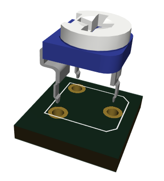 |
| Pasul 4 | Cositorește ledurile, astfel încât terminalul mai lung (cel pozitiv adică) să corespundă semnului "+" de pe PCB | |
| Pasul 5 | Cositorește soclurile, astfel încât marcajele decupate să corespundă celor de pe PCB | |
| Pasul 6 | Cositorește conectorul pentru alimentare conform marcajului de pe PCB | 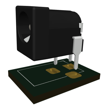 |
| Pasul 7 | Introdu circuitele integrate 555 si 4017 in soclul lor, astfel încât marcajele decupate să corespundă celor de pe PCB | |
| Pasul 8 | Alimentează circuitul prin metoda aleasă inițial și verifică daca LED-urile se aprind rând pe rând | 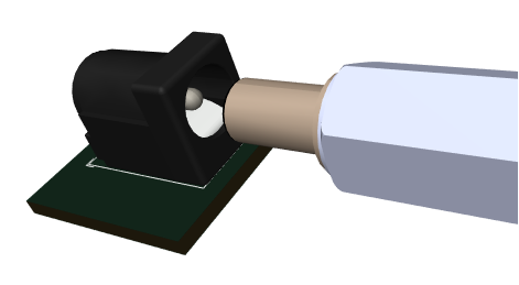 |
| Pasul 9 | Ajustează viteza cu care lumina trece de la un LED la celălalt prin rotirea lentă a trimmerului R13 | 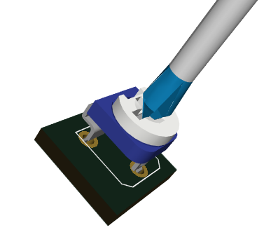 |
| Pasul 10 | Buzură-te de circuitul tău! |  |
Instrucțiuni generale de asamblare în vederea respectării garanției
Ca o măsură de precauție și pentru respectarea condițiilor de garanție, recomandăm testarea fiecărei componente în parte înainte de momentul asamblării. De exemplu, rezistorilor li se va măsura valoarea cu un ohmmetru/multimetru. Kiturile sunt garantate pe fiecare componentă în parte, nu pe tot ansamblul. Deoarece asamblarea se face de către personal neautorizat, în condiții necunoscute sau în stadii necunoscute de finalizare, nu ne putem asuma nicio răspundere legală legată de orice urmări sau de funcționarea dispozitivelor asamblate de către orice terță parte.