Brad de Crăciun luminos DIY
Introducere
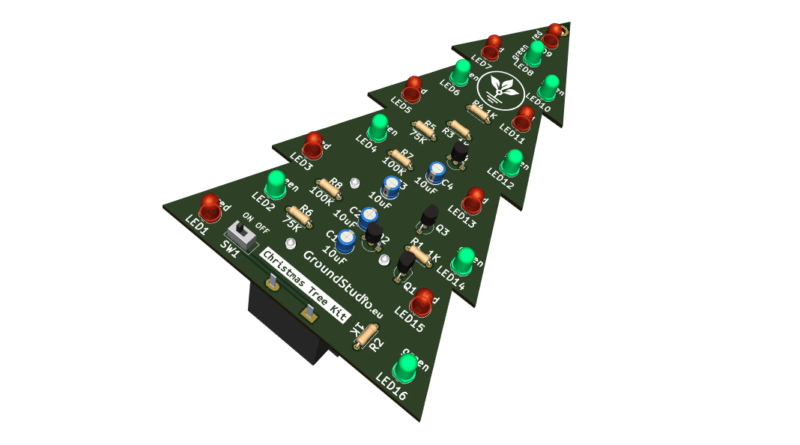
Acest circuit simulează jocul de lumini al unui brad de Crăciun. Este format din 16 LED-uri, 8 roșii și 8 verzi, împărțite în 4 zone care se aprind si se sting la frecvențe diferite. Spre deosebire de alte circuite generator de lumină intermitentă care folosesc circuite integrate, circuitul din acest kit utilizează doar tranzistoare ca elemente active. Poate fi alimentat de la o baterie de 9V și utilizat ca dispozitiv independent.
Lista cu uneltele necesare asamblării și funcționării
neincluse in kit
| Nume | Imagine | Cumpără |
|---|---|---|
| Letcon | 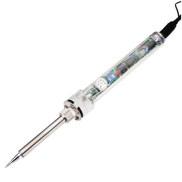 | |
| Fludor | 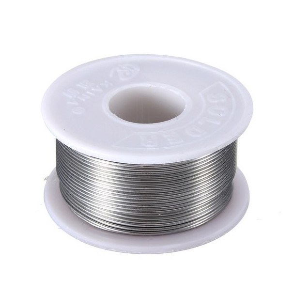 | |
| Clește pentru fire |  | |
| Șurubelniță Phillips (în cruce) | 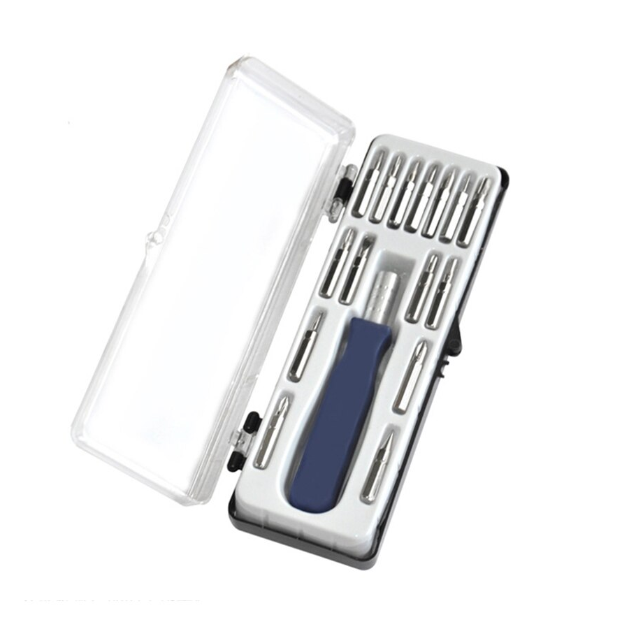 | |
| Baterie 9V | 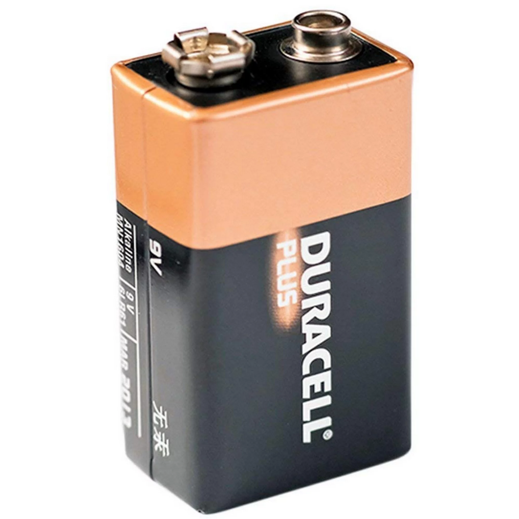 |
Listă cu componentele incluse în kit
| Qty | Nume | Detalii | Footprint | Imagine |
|---|---|---|---|---|
| 4 | Rezistor | 1K | R1 – R4 | 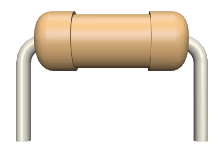 |
| 2 | Rezistor | 75K | R5, R6 | |
| 2 | Rezistor | 100K | R7, R8 | |
| 8 | LED | 5mm, roșu | LED1, LED3, LED5, LED7, LED9, LED11, LED13, LED15 | 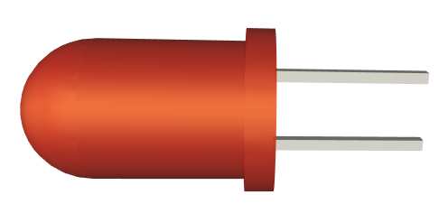 |
| 8 | LED | 5mm, green | LED2, LED4, LED5, LED8, LED10, LED12, LED14, LED16 | |
| 4 | Tranzistor | 8050, bipolar NPN | Q1 – Q4 | |
| 4 | Condensator electrolitic | 10uF | C1 – C4 | 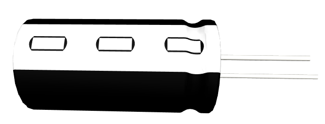 |
| 1 | Buton slider | SW1 | 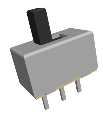 | |
| 1 | Suport de baterie | 9V | J1 | 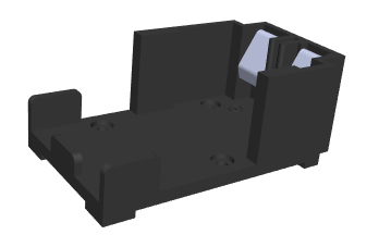 |
| 1 | PCB | 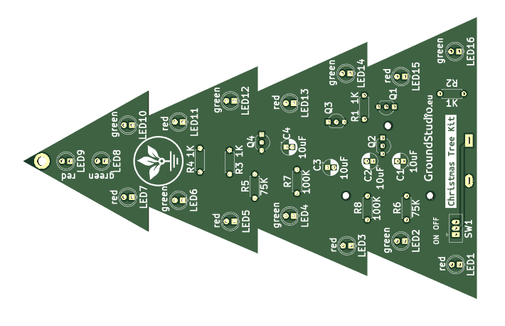 |
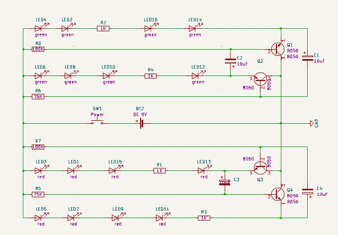
Schema electronică
Principiul de funcționare
Circuitul este compus din două multivibratoare bistabile (flip-flop):
- Primul este format din tranzistorii Q1 și Q2, împreună cu condensatorii C1 și C2, și controlează intermitent ramurile de LED-uri LED4-LED14 și LED6-LED12.
- Cel de-al doilea este format din tranzistorii Q3 și Q4, împreună cu condensatorii C3 și C4, și controlează intermitent ramurile de LED-uri LED4-LED14 și LED6-LED12.
Fiecare bistabil, așa cum sugerează și numele, are două stări. În cazul nostru, aceste stări sunt intermitente. Cu cele două bistabile, fiecare având două stări, avem în total 4 stări care formează jocul de lumină.
Observând lumina intermitentă, putem vedea că cele 4 stări au frecvențe diferite. Frecvența schimbării stării depinde de tensiunea dintre baza și emițătorul tranzistoarelor. Ambele bistabile sunt alimentate la aceeași tensiune, au condensatoare și rezistoare de aceleași valori, și același număr de LED-uri... ce face ca tensiunea bază-emițător a celor două bistabile să difere? Ei bine, este culoarea LED-urilor. LED-urile verzi au o cădere de tensiune mai mare decât LED-urile roșii. Astfel, avem un dezechilibru, o diferență de tensiune între cele două bistabile, rezultând în frecvențe de blink diferite.
Instrucțiuni pentru pregătirea asamblării
| Pasul 0 | Citește toate instrucțiunile, de la început și până la sfârșit. |
| Pasul 1 bis | Reminder: E foarte important să citești toate instrucțiunile din acest document |
| Pasul 1 | Asigură-te că ai toate uneltele necesare asamblării kitului. |
| Pasul 2 | Asigură-te că ai toate componentele necesare asamblării kitului. |
| Pasul 3 | Pentru a respecta condițiile de garanție*, verifică/măsoară fiecare componentă în parte. |
Instrucțiuni de asamblare
| Step | Detalii | Imagine |
|---|---|---|
| Pasul 1 | Cositorește rezistorii conform marcajelor de pe PCB, indiferent de orientare. Ai grijă să respecți valorile și marcajele | |
| Pasul 2 | Cositorește ledurile, astfel încât terminalul mai lung (cel pozitiv adică) să corespundă semnului "+" de pe PCB | |
| Pasul 3 | Cositorește condensatorii electrolitici, astfel încât terminalul mai scurt (cel negativ, catodul) să corespundă zonei hașurate de pe PCB | |
| Pasul 4 | Cositorește tranzistorul conform marcajului de pe PCB | |
| Pasul 5 | Cositorește butonul SW1 conform marcajului de pe PCB, indiferent de orientare | 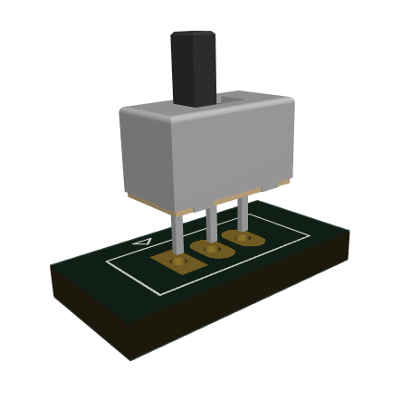 |
| Pasul 6 | Fixeaza cu suruburi suportul de baterie | 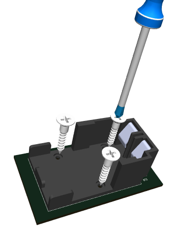 |
| Pasul 7 | Cositorește suportul de baterie | 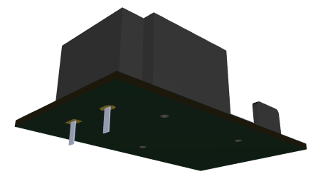 |
| Pasul 8 | Introdu bateria de 9V si pune butonul slider pe pozitia ON | 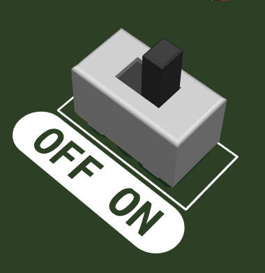 |
| Pasul 9 | Bucură-te de Bradul tău de Crăciun luminos! |  |
Instrucțiuni generale de asamblare în vederea respectării garanției
Ca o măsură de precauție și pentru respectarea condițiilor de garanție, recomandăm testarea fiecărei componente în parte înainte de momentul asamblării. De exemplu, rezistorilor li se va măsura valoarea cu un ohmmetru/multimetru. Kiturile sunt garantate pe fiecare componentă în parte, nu pe tot ansamblul. Deoarece asamblarea se face de către personal neautorizat, în condiții necunoscute sau în stadii necunoscute de finalizare, nu ne putem asuma nicio răspundere legală legată de orice urmări sau de funcționarea dispozitivelor asamblate de către orice terță parte.