VU-meter
Introduction
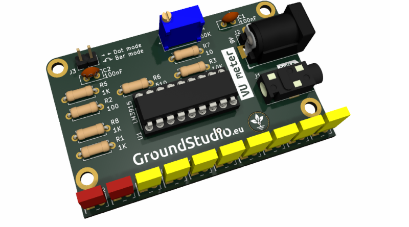
This VU meter, short for “Volume Unit meter,” is an educational tool used to introduce students and electronics enthusiasts to the field of audio signal measurement and display. The kit is designed to provide a visual representation of the audio signal level, making it easier to monitor and control the volume of audio equipment. It does not provide an exact numerical measurement but offers a relative indication of volume.
List of tools required for assembly and operation,
not included in the kit
| Name | Image | Buy here |
|---|---|---|
| Soldering iron |  | |
| Solder wire |  | |
| Pliers |  | |
| Helping hands (device or a friend) |  | |
| Flathead screwdriver |  | |
| Audio source* | ||
| 9V Power supply** |
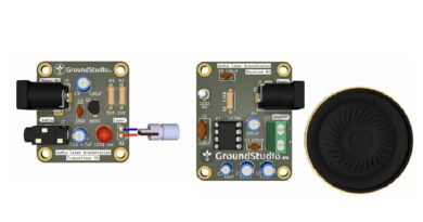
* As an audio source, we recommend an inexpensive device, such as this Bluetooth receiver, to be connected to the kit. If the kit is not properly assembled, the audio device can become damaged. Do not use a smartphone wire connected to the kit,
| Bluetooth reveiver + Jack 3.5 cable | 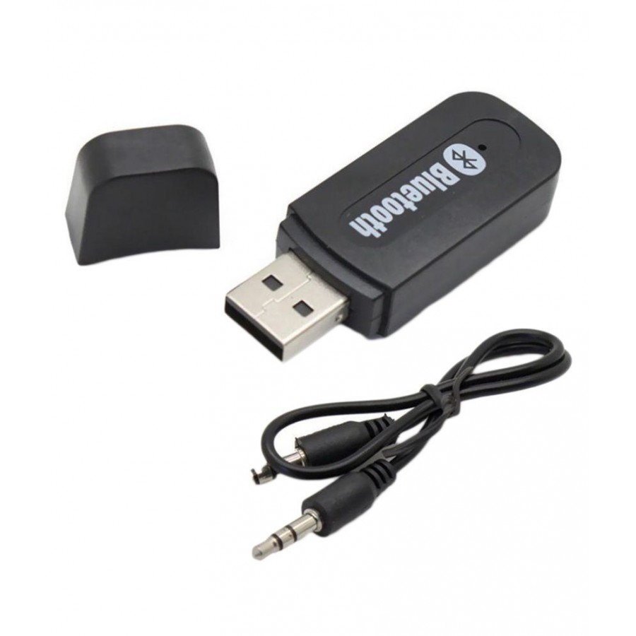 | |
| 5V USB power supply | 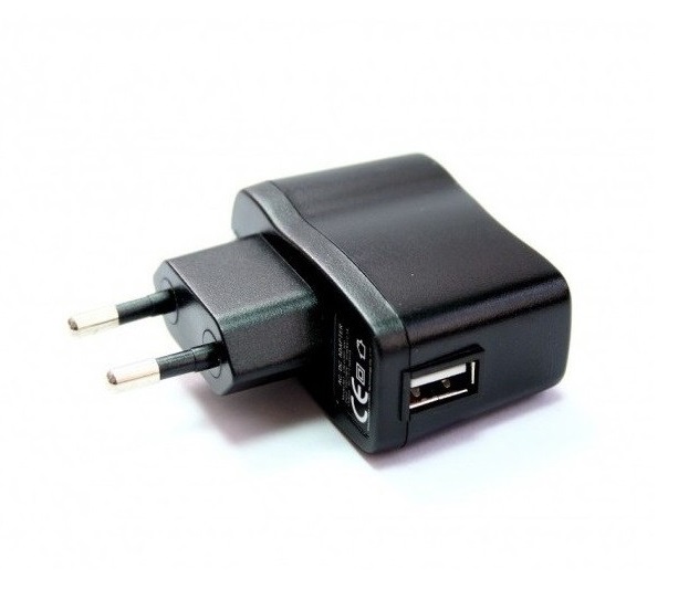 |
**To power the circuit, you’ll need a 9V power supply with a DC connector.
Here are some suggestions:
| Connector for 9V battery + battery | 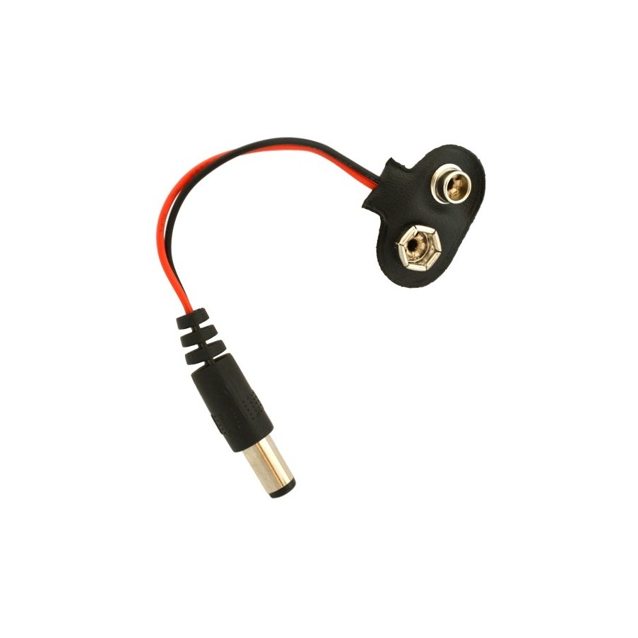 + 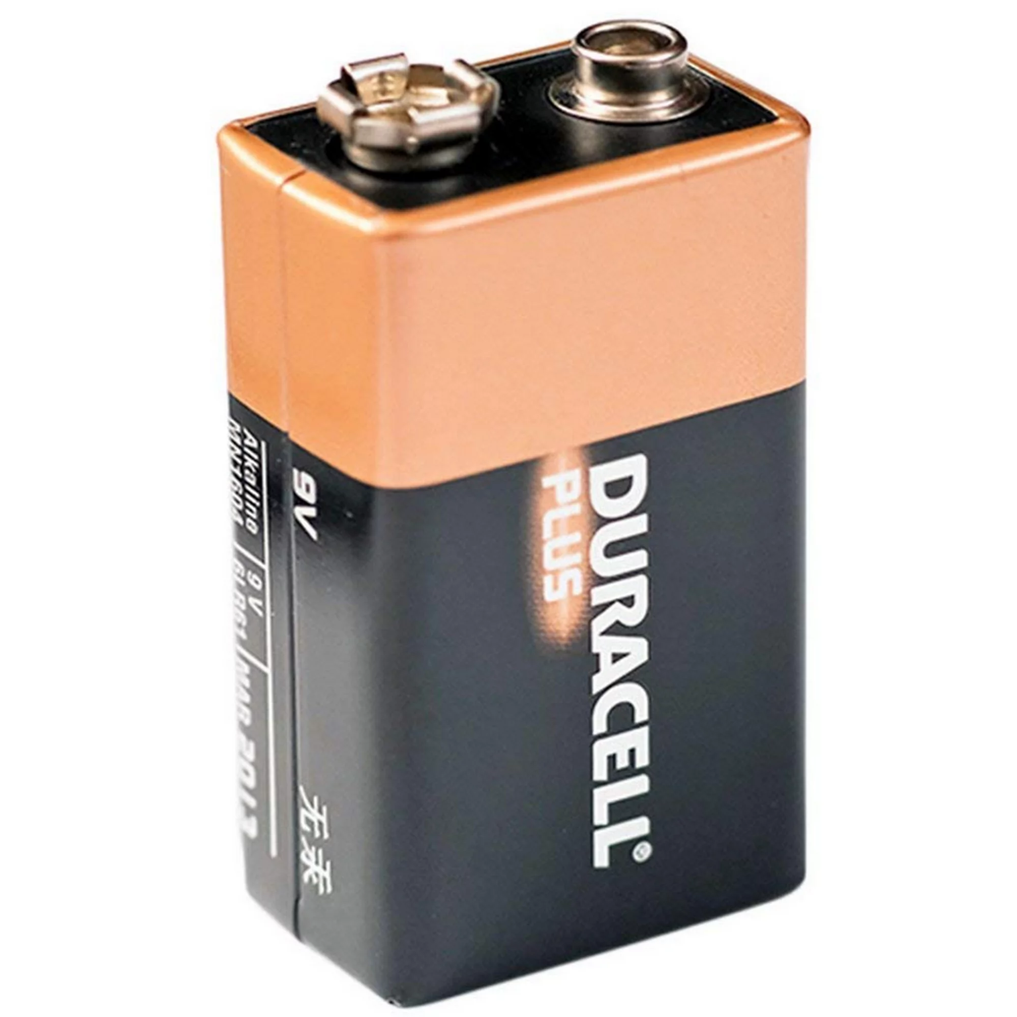 | |
| 9V power supply | 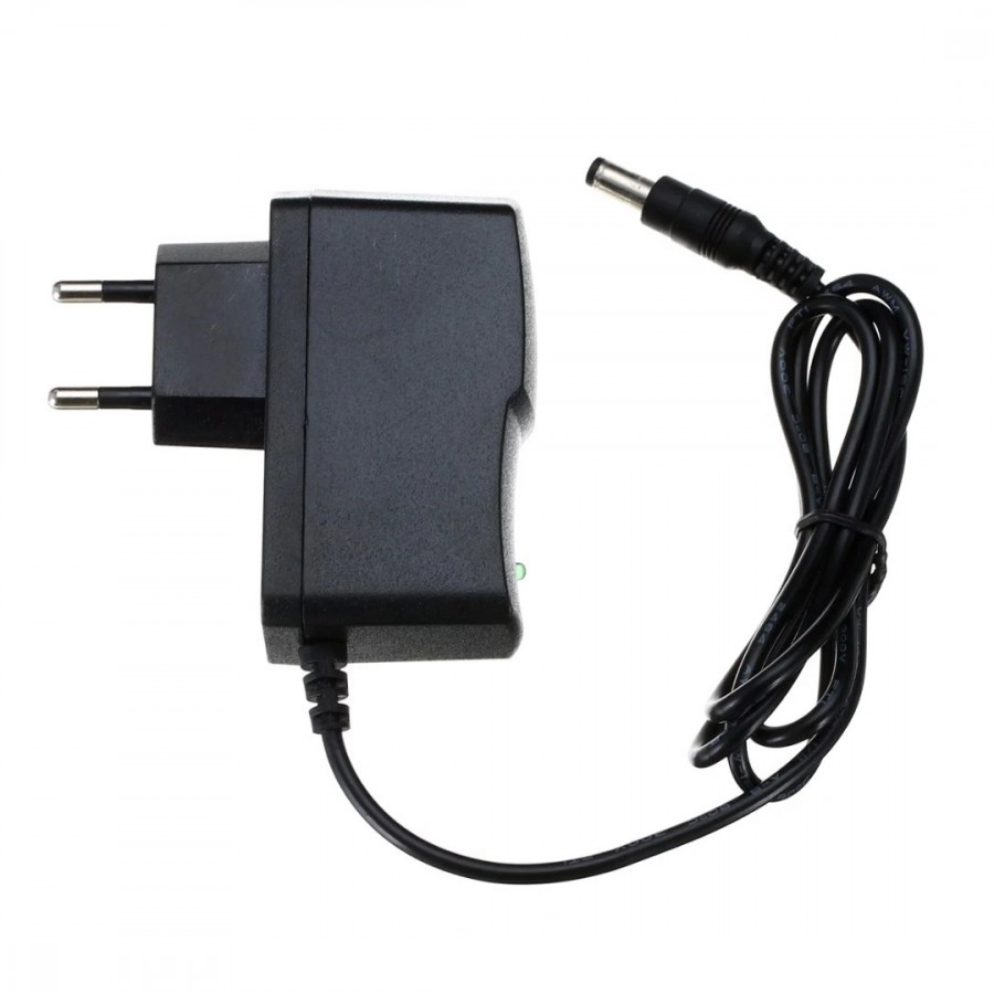 |
List of components included in the kit
| Quantity | Name | Details | Footprint | Image |
|---|---|---|---|---|
| 3 | Resistor | 1K | R1, R5, R8 | 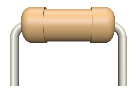 |
| 1 | Resistor | 100 | R2 | |
| 1 | Resistor | 10K | R3 | |
| 1 | Resistor | 10 | R7 | |
| 1 | Resistor | 20K | R9 | |
| 1 | Resistor | 560 | R6 | |
| 1 | Potentiometer | 50K | R4 | 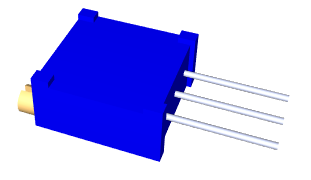 |
| 8 | LED | Yellow, rectangular | LED1-LED8 | 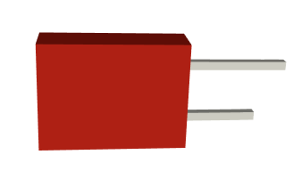 |
| 2 | LED | Red, rectangular | LED9, LED10 | |
| 3 | Ceramic capacitor | 100nF | C1-C2 | 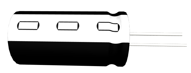 |
| 1 | Power connector | jack barrel, 9V | J2 | 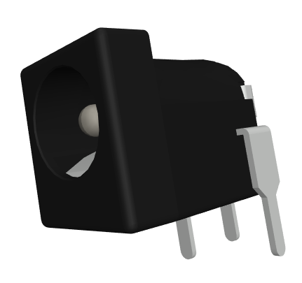 |
| 1 | Audio jack connector | 3.5mm | J1 | 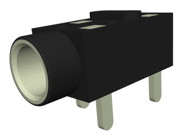 |
| 1 | Pin header | 2 pins, male | J3 | 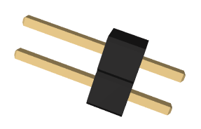 |
| 1 | Jumper connector | 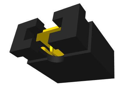 | ||
| 1 | Integrated circuit | LM3915 | U1 | 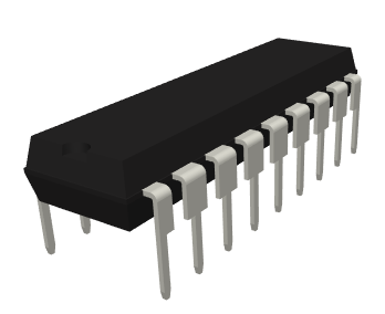 |
| 1 | Socket | 18 pin | U1 | 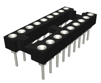 |
| 1 | PCB | 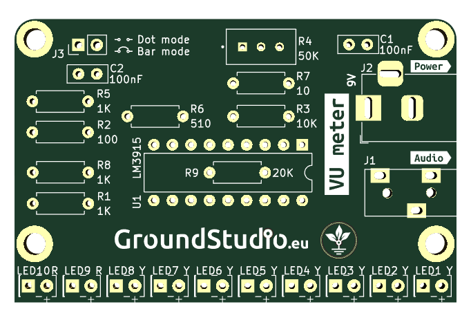 |
Schematic
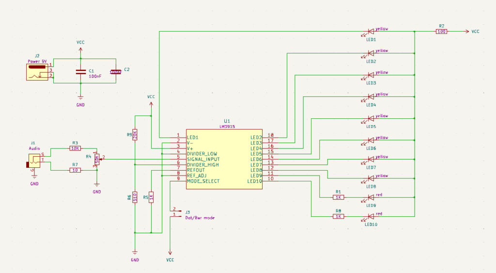
Working principle
The circuit is based on the LM3915 integrated circuit, which provides functions such as audio signal display and monitoring. An external device that generates the audio signal ( an MP3 player, a radio, or a Bluetooth receiver with audio output) is connected to the jack socket on the board.
The audio signal (voltage), is directed to pin 5 of the integrated circuit, the pin responsible for signal reading. Depending on the voltage level of the input signal, the integrated circuit will light up the LEDs from LED1 to LED10.
There are two ways to display the audio signal on the LEDs. Pin 9 functions as the mode selection:
- Dot mode: displaying only one LED at a time, which we’ll call LEDmax, based on the current maximum level of the audio signal. To select this mode, leave connector J3 open, without a jumper (meaning the voltage is 0 on pin 9).
- Bar mode: illuminating all LEDs from LED1 to LEDmax. To select this mode, place the jumper on connector J3 (meaning pin 9 is connected to ground).
If the audio signal is too large to be displayed correctly (LEDs remain predominantly lit) or too small (they don’t light up or only a few do), you can adjust the input signal using a voltage divider. Potentiometer R4 serves this purpose and should be adjusted to ensure the signal fits well within the entire LED range.
WARNING
Do not use your smartphone or other expensive or valuable devices as a sound genetator directly connected to your kit. There is a risk of damage if the kit is not correctly assembled. Our recommendation is a Bluetooth receiver instead.
Instructions for assembly preparation
| Step 0 | Read all the instructions, from beginning to end. |
| Step 0 bis | Reminder: It is very important to read all the instructions. |
| Step 1 | Make sure you have all the tools needed to assemble the kit. |
| Step 2 | Make sure you have all the components needed to assemble the kit. |
| Step 3 | To comply with the warranty conditions*, check/measure each component separately. |
Assembly instructions
| Step | Details | Image |
|---|---|---|
| Step 1 | Solder the resistors according to the markings on the PCB, regardless of orientation. Make sure you respect the values and markings | |
| Step 2 | Solder the ceramic capacitors, regardless of orientation | |
| Step 3 | Solder the LEDs so that the longer terminal (the positive one) corresponds to the “+” sign on the PCB | 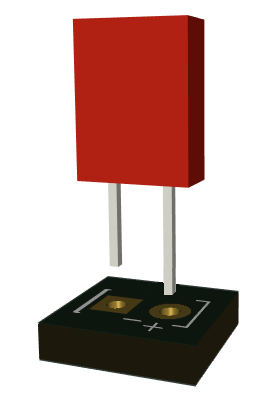 |
| Step 4 | Solder the socket so that the cut-out markings correspond to those on the PCB | |
| Step 5 | Solder the potentiometer, so that the screw is oriented toward the point marked on the PCB. | 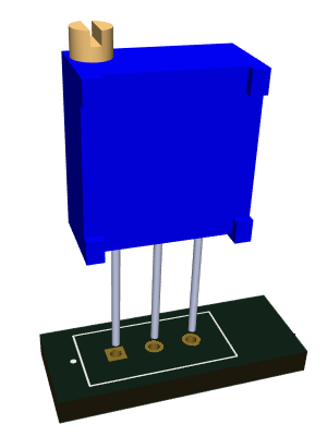 |
| Step 6 | Solder the J3 jumper. regardless of orientation | 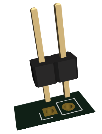 |
| Step 7 | Solder the power connector according to the marking on the PCB | 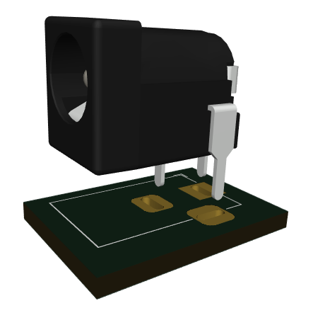 |
| Step 8 | Solder the audio connector according to the marking on the PCB | 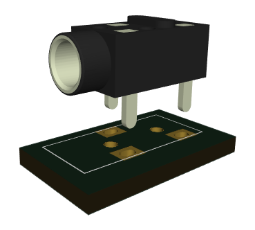 |
| Step 9 | Insert the LM3915 integrated circuit in its socket, so that the cut-out marking correspond to the one on the PCB | |
| Step 10 | Link the bluetooth receiver to your smartphone, play your favourite music, and connect the audio cable to the kit | 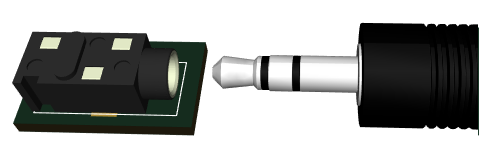 |
| Step 11 | Power the circuit with the chosen power supply | 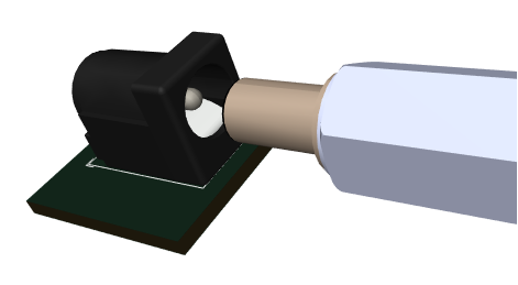 |
| Step 12 | Adjust the potentiometer until the signal is properly displayed on all the LEDs | 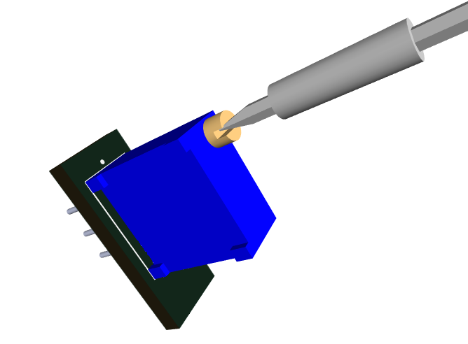 |
| Step 13 | Select the display mode, bar or dot, by placing the jumper on the J3 connector or not. | 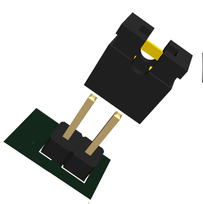 |
| Step 14 | Enjoy your VU-meter |  |
General assembly instructions for Warranty Compliance
As a precaution and to comply with the warranty conditions, we recommend testing each individual component before assembly. For example, resistors will be measured with an ohmmeter/multimeter. The warranty is for each individual component, not for the whole assembly. Since assembly is done by unauthorized personnel, under unknown conditions or at unknown stages of completion, we cannot assume any legal liability related to any consequences or operation of devices assembled by any third party.