Transmisie audio prin laser
Introducere
Cu ajutorul acestui kit putem transmite semnale audio wireless de pe o placă pe alta, doar prin intermediul luminii emise de o diodă laser.
Lista cu uneltele necesare asamblării și funcționării
neincluse in kit
| Nume | Imagine | Cumpără |
|---|---|---|
| Letcon |  | |
| Fludor |  | |
| Clește pentru fire |  | |
| Helping hands (dispozitivul sau un prieten) |  | |
| Sursă audio* | ||
Sursă de alimentare 9V** |
* Cu sursă audio, recomandăm un dispozitiv ieftin, precum acest receptor Bluetooth, pentru a fi conectat la kit. Dacă kitul nu este asamblat corect, dispozitivul audio poate fi deteriorat. Nu utilizați un smartphone conectat prin fir la kit.,
| Receiver Bluetooth + Cablu cu mufă Jack 3.5 | 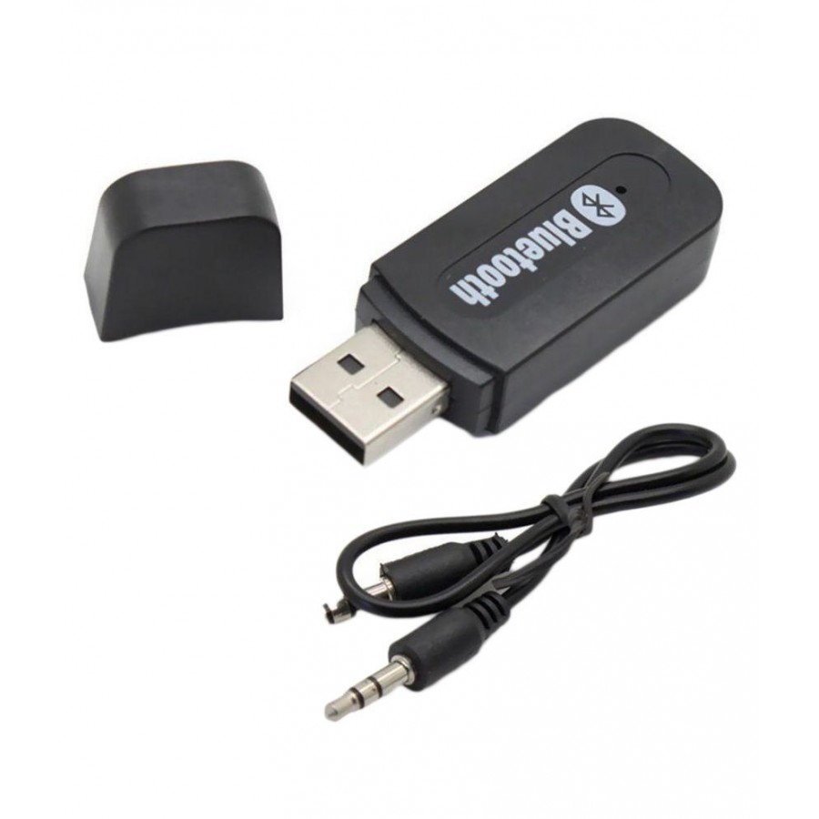 | |
| Sursă de alimentare USB 5V | 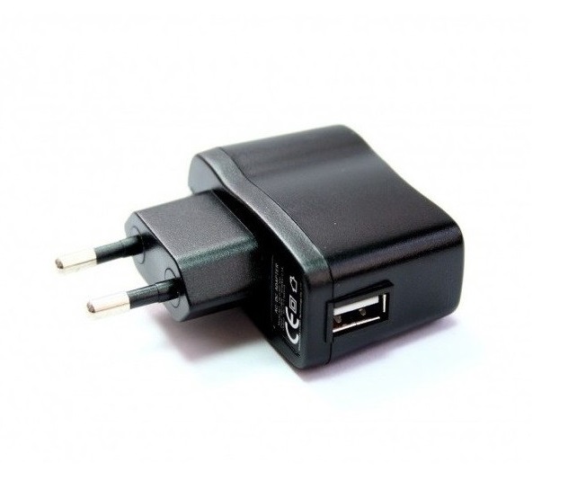 |
**Pentru a alimenta circuitul, ai nevoie de o sursă de tensiune de 9V cu conector DC.
Iată câteva sugestii:
| Conector pentru baterie de 9V + baterie | 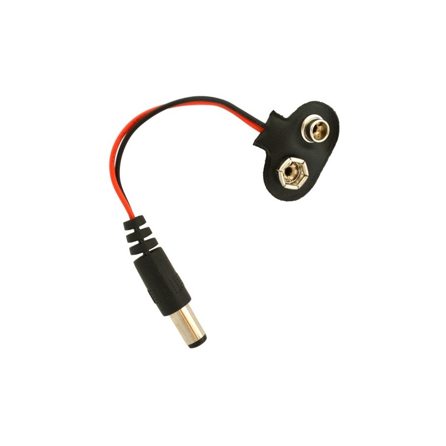 + 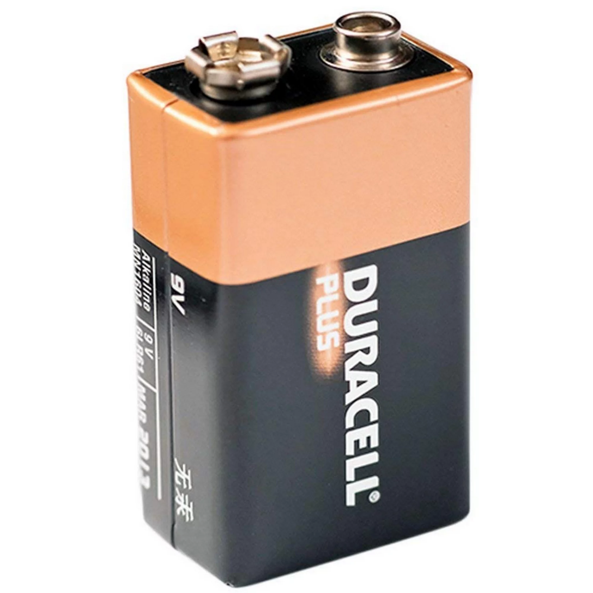 | |
| Alimentator de 9V | 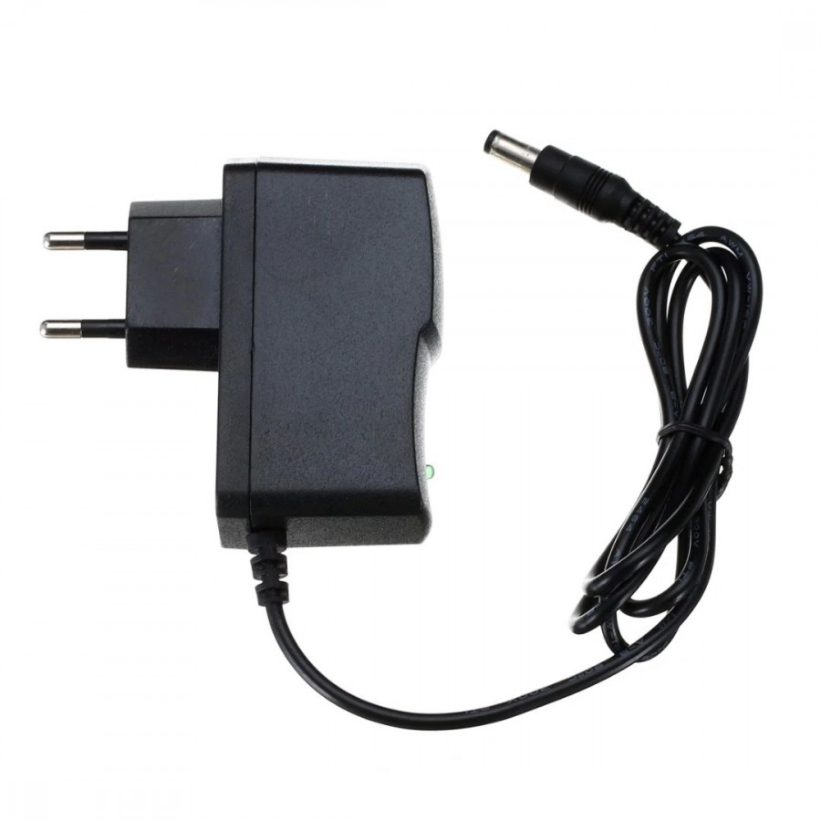 |
Listă cu componentele incluse în kit
| Qty | Nume | Detalii | Footprint | Imagine |
|---|---|---|---|---|
| 1 | Rezistor | 620K | R1 | 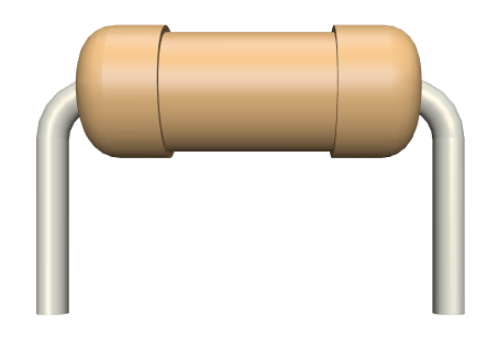 |
| 1 | Rezistor | 100R | R2 | |
| 1 | Rezistor | 51K | R3 | |
| 1 | Diodă laser | roșu | D2 | 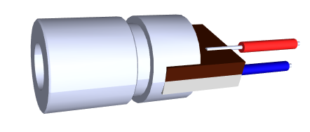 |
| 1 | Fotodiodă | D1 | ||
| 1 | Condensator electrolitic | 10uF | C2 | 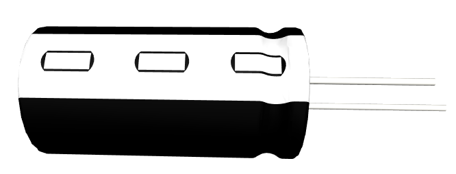 |
| 4 | Condensator electrolitic | 100uF | C3, C5, C7, C9 | |
| 1 | Condensator electrolitic | 4.7uF | C10 | |
| 1 | Condensator ceramic | 220nF | C1 | 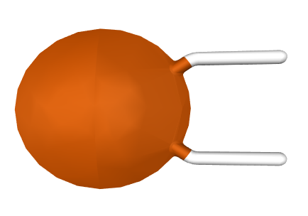 |
| 2 | Condensator ceramic | 100nF | C4, C6 | |
| 1 | Condensator ceramic | 10nF | C8 | |
| 2 | Tranzistor | 8050 | Q1 | |
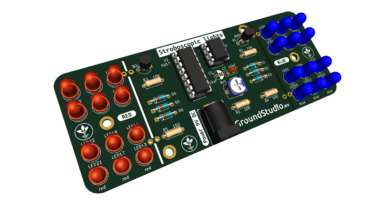
| 12 | LED | roșu, 5mm | LED1 | 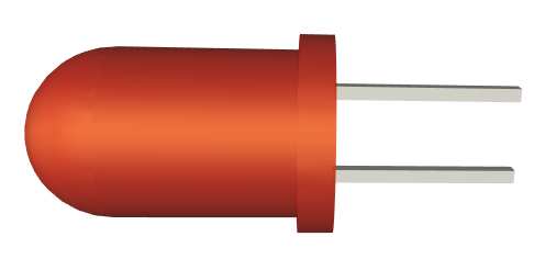 |
| 1 | Circuit integrat | LM386 | U1 | 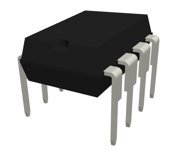 |
| 1 | Soclu | 8 pins | U1 | 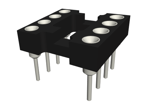 |
| 2 | Conector pentru alimentare | jack barrel, 9V | J1, J3 | 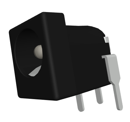 |
| 1 | Audio connector | jack 3.5 | J2 | 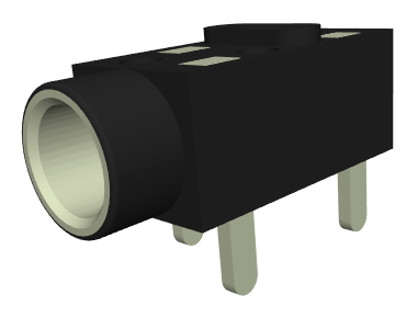 |
| 1 | Difuzor | 8ohm | 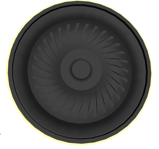 | |
| 1 | Cablu pentru difuzor | |||
| 1 | PCB | 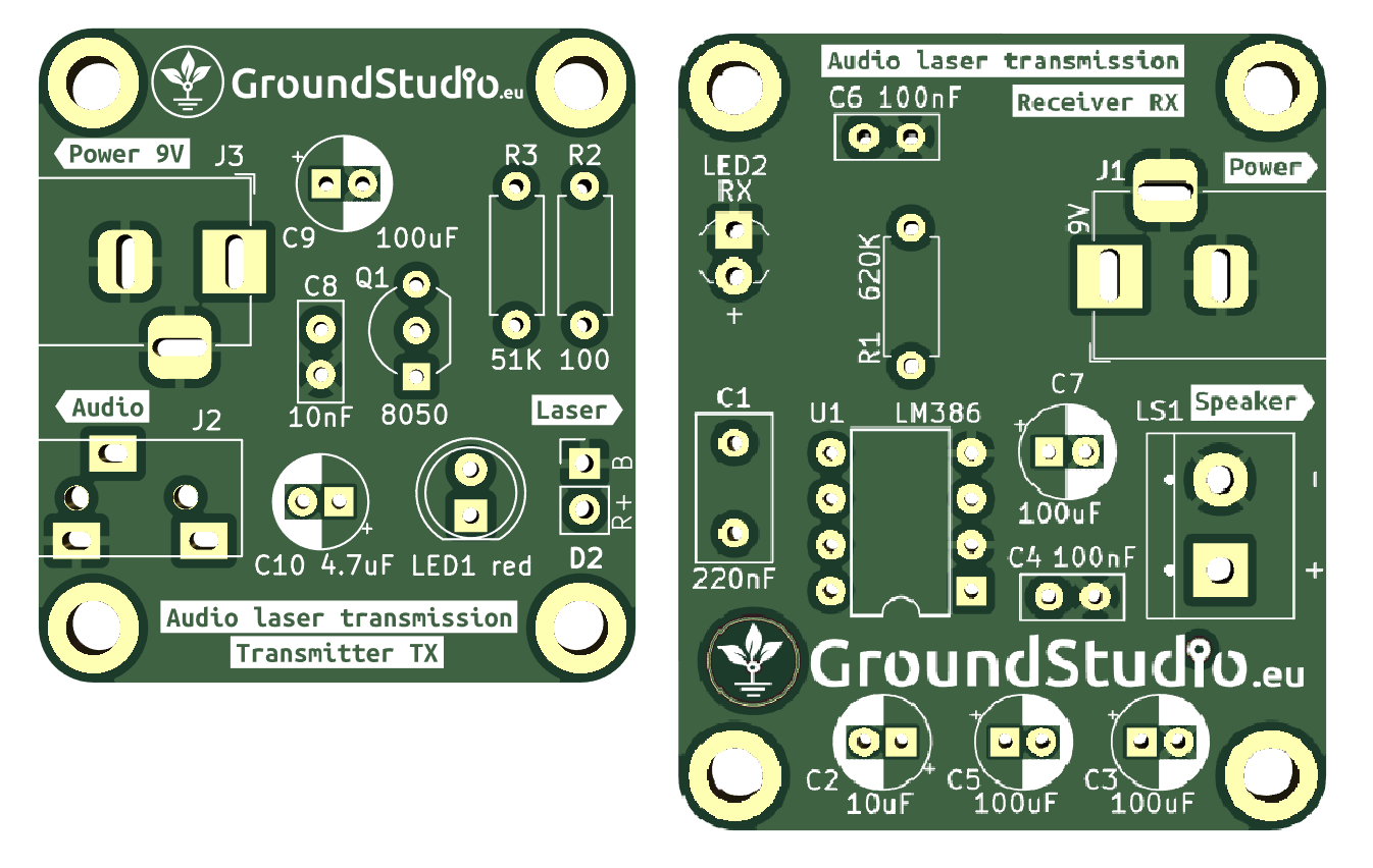 |
Schema electronică
Principiul de funcționare
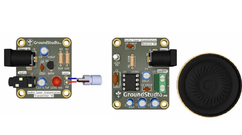
Circuitul constă din două părți: emițător și receptorul. Sursa semnalului audio este conectată la transmitor, iar receptorul redă semnalul audio printr-un difuzor.
Emițător (TX)
Ca element de intrare în emițător , avem semnalul audio (prin conectorul jack J2) și o sursă de tensiune de 9V (conectorul J3). Ieșirea este lumina generată de dioda laser D2. Semnalul audio este în general un semnal slab cu o formă alternantă (atât negativă, cât și pozitivă). Rolul tranzistorului bipol NPN 8050 este de a deplasa semnalul audio către o tensiune pozitivă astfel încât să poată aprinde dioda laser. Fără această deplasare, dioda laser nu s-ar ilumina și nu ar putea transmite semnalul către cealaltă placă.
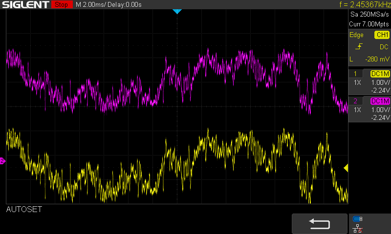
În captura de ecran de mai jos, două sonde sunt conectate la osciloscop:
- Galben pentru semnalul audio de intrare
- Violet pentru semnalul de pe dioda laser. Se poate observa că semnalul galben este centrat în jurul valorii de 0V, în timp ce semnalul violet este deplasat cu aproximativ 3V. Acești 3V reprezintă tensiunea necesară pentru ca dioda laser să se ilumineze, cu intensitate luminată variabilă, în funcție de valoarea tensiunii din semnal.
Receptor (RX)
Componentele cheie ale receptorului sunt photodioda, amplificatorul audio LM386 și difuzorul. Semnalul luminos transmis de dioda laser este recepționat de fotodiodă. Atunci când fotodioda este expusă la lumină, generează electricitate (efect fotovoltaic). Amplificatorul LM386 amplifică tensiunea generată de fotodiodă, având o tensiune de alimentare semnificativ mai mare (9V pe pinul 1-GAIN) decât tensiunea generată de fotodiodă(în milivolți). Semnalul amplificat este apoi redat prin difuzor, devenind astfel audibil.
Instrucțiuni pentru pregătirea asamblării
| Pasul 0 | Citește toate instrucțiunile, de la început și până la sfârșit. |
| Pasul 1 bis | Reminder: E foarte important să citești toate instrucțiunile din acest document |
| Pasul 1 | Asigură-te că ai toate uneltele necesare asamblării kitului. |
| Pasul 2 | Asigură-te că ai toate componentele necesare asamblării kitului. |
| Pasul 3 | Pentru a respecta condițiile de garanție*, verifică/măsoară fiecare componentă în parte. |
Instrucțiuni de asamblare
| Step | Detalii | Imagine |
|---|---|---|
| Pasul 1 | Cositorește rezistorii conform marcajelor de pe PCB, indiferent de orientare. Ai grijă să respecți valorile și marcajele | |
| Pasul 2 | Cositorește condesatorii ceramici, indiferent de orientare | |
| Pasul 3 | Cositorește condensatorii electrolitici, astfel încât terminalul mai scurt (cel negativ, catodul) să corespundă zonei hașurate de pe PCB | |
| Pasul 4 | Cositorește tranzistorul, astfel încât marcajul decupat să corespundă celui de pe PCB | |
| Pasul 5 | Solder the LED and the photodiode so that the longer terminal (the positive one) corresponds to the “+” sign on the PCB | |
| Pasul 6 | Cositorește soclul, astfel încât marcajul decupat să corespundă celui de pe PCB | |
| Pasul 7 | Cositorește conectorul pentru alimentare conform marcajului de pe PCB | 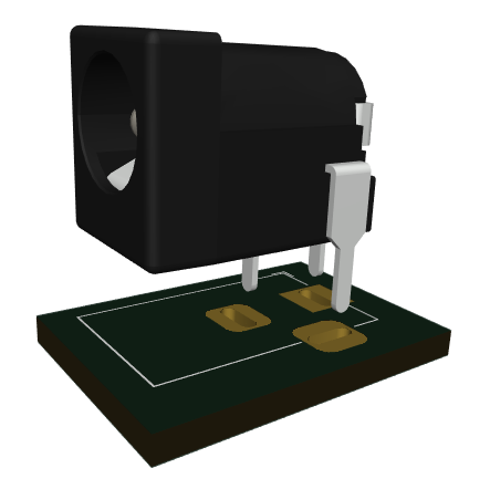 |
| Pasul 8 | Cositorește conectorul audio conform marcajului de pe PCB | 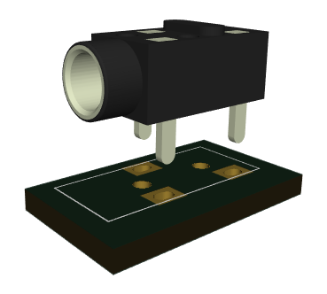 |
| Pasul 9 | Introdu circuitel integrat in soclu, astfel încât marcajul decupat să corespundă celui de pe PCB | |
| Pasul 10 | Cositoreste dioda laser pe padul marcat "Laser", firul albastru la B si firul rosu la R | 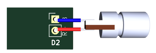 |
| Pasul 11 | Alimentează circuitul cu sursa aleasă | 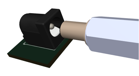 |
| Pasul 12 | Conectează smartphone-ul prin Bluetooth la receiver, pornește muzica preferată și conecteaza receiverul la kit prin cablul audio |  |
| Pasul 13 | Îndreaptă dioda laser către LED-ul transparent | 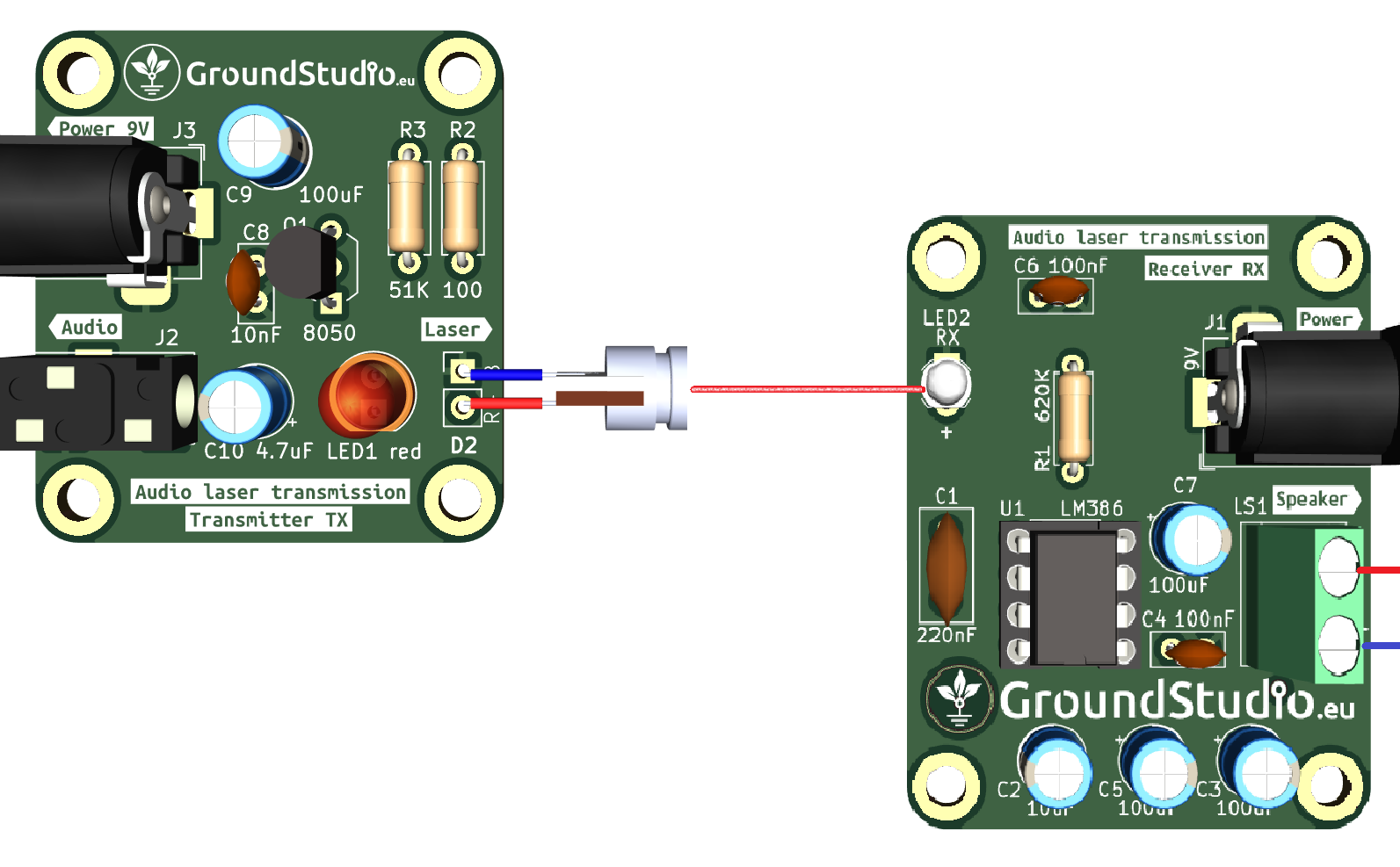 |
| Step 14 | Bucură-te de muzica ta transmisă prin laser! |  |
Instrucțiuni generale de asamblare în vederea respectării garanției
Ca o măsură de precauție și pentru respectarea condițiilor de garanție, recomandăm testarea fiecărei componente în parte înainte de momentul asamblării. De exemplu, rezistorilor li se va măsura valoarea cu un ohmmetru/multimetru. Kiturile sunt garantate pe fiecare componentă în parte, nu pe tot ansamblul. Deoarece asamblarea se face de către personal neautorizat, în condiții necunoscute sau în stadii necunoscute de finalizare, nu ne putem asuma nicio răspundere legală legată de orice urmări sau de funcționarea dispozitivelor asamblate de către orice terță parte.