Zar electronic din LED-uri
Introducere
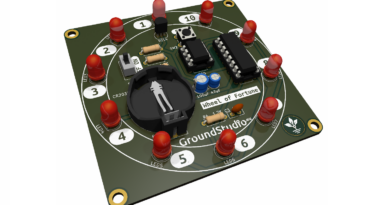
Acest circuit simuleaza aruncarea zarului. La simpla apasare a butonului, va porni un joc de lumini scurt si aleator pe cele 7 leduri. Apoi ledurile vor ramane aprinse sub forma unei fatete de zar, reprezentand un numar aleator intre 1 si 6.
Uneltele necesare asamblării și funcționării, neincluse in kit
| Nume | Imagine | Buy Here |
|---|---|---|
| Letcon | 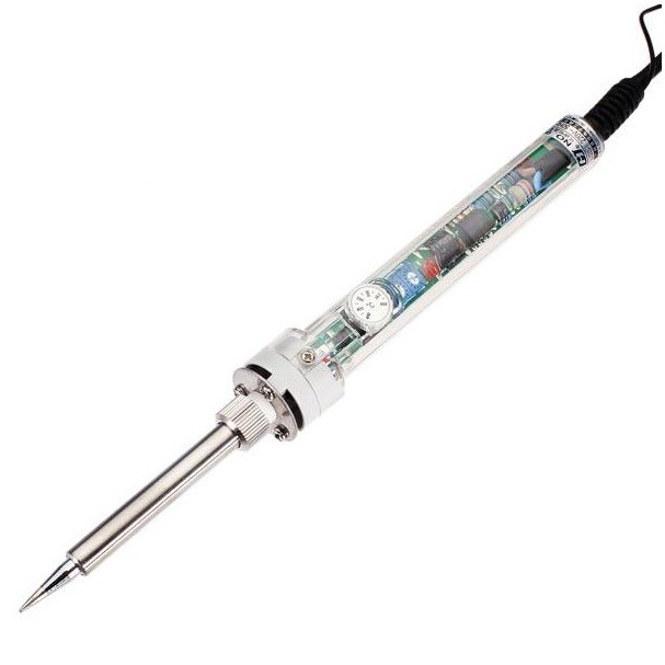 | |
| Fludor | 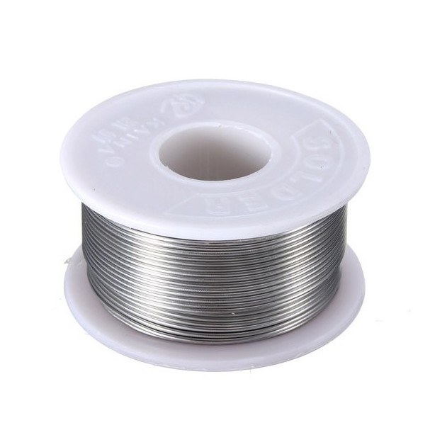 | |
| Clește pentru fire |  | |
| Helping hands (dispozitivul sau un prieten) | 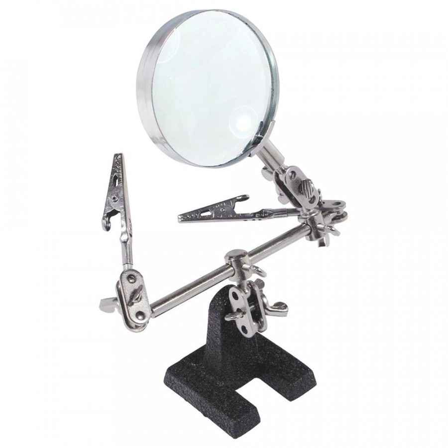 | |
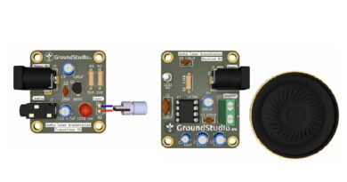
| Sursă de alimentare de 9V |
*To power the circuit, you‘ll need a 9V power supply with a DC connector.
Iată câteva sugestii:
| Nume | Imagine | Buy Here |
|---|---|---|
| Conector pentru baterie de 9V + baterie | 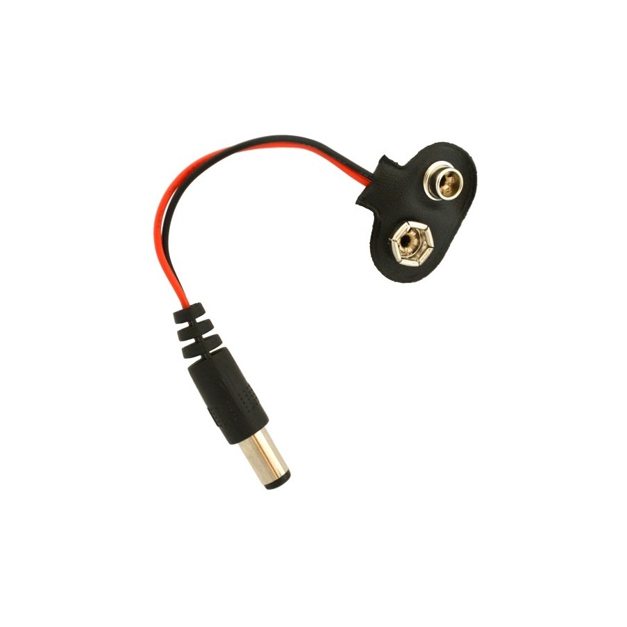 + 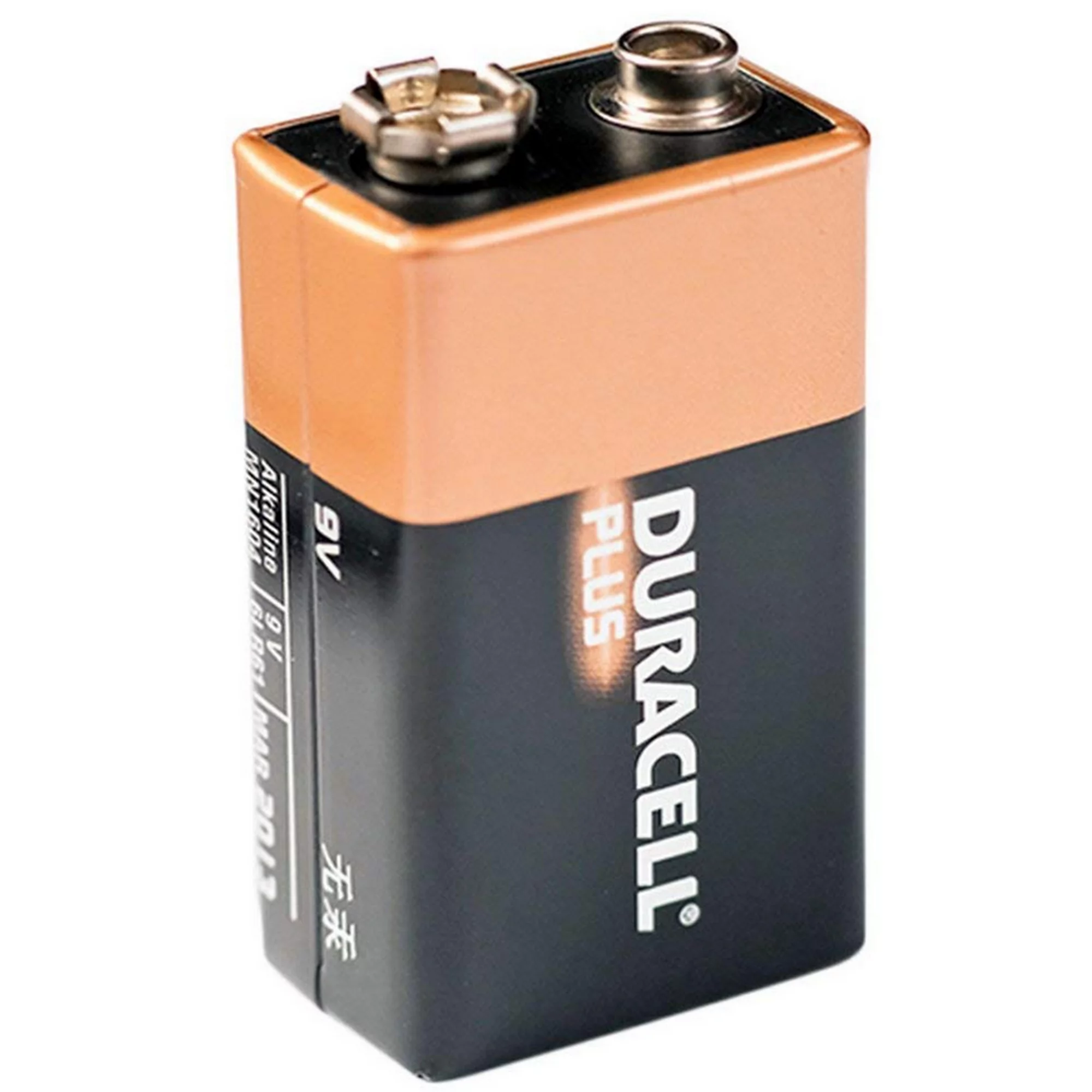 | |
| Alimentator de 9V | 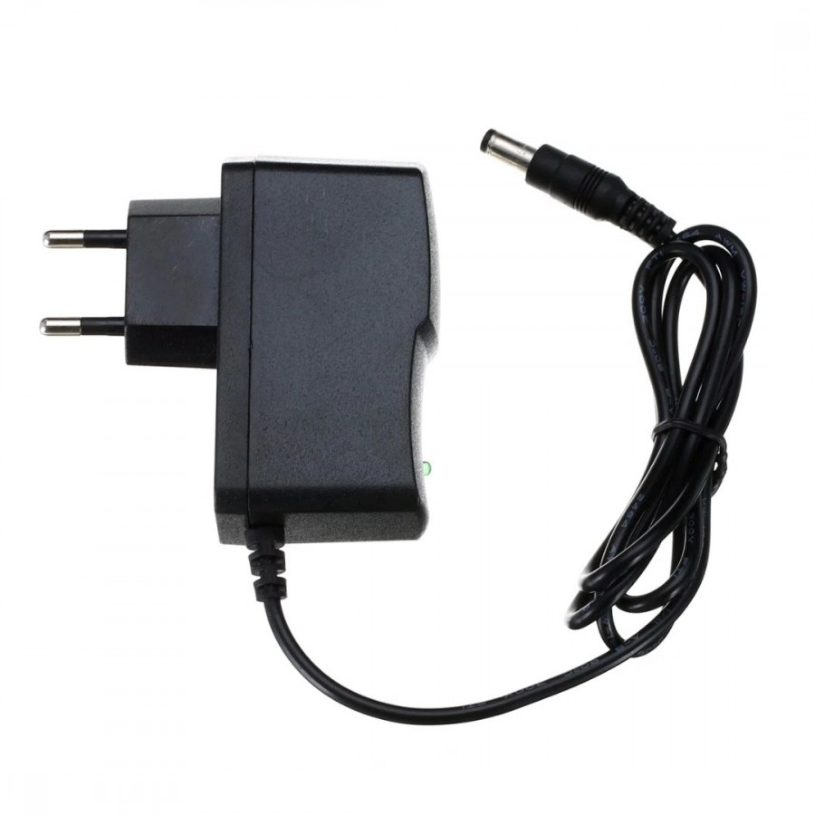 |
Componentele incluse în kit
| Qty | Nume | Detalii | Footprint | Imagine |
|---|---|---|---|---|
| 2 | Rezistor | 470K, 1/4W | R1, R3 | 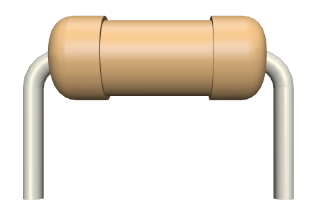 |
| 1 | Rezistor | 20K, 1/4W | R2 | |
| 4 | Rezistor | 2.2K, 1/4W | R4-R7 | |
| 8 | Diode | N4148 | D1-D8 | |
| 7 | LED | 5mm, roșu | LED1-LED7 | 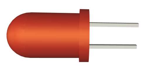 |
| 1 | Tranzistor | S9014 | Q1 | |
| 1 | Condensator electrolitic | 47uF, 16V | C1 | 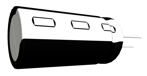 |
| 1 | Condensator electrolitic | 4.7uF, 50V | C2 | |
| 1 | Buton | 6x6mm | SW1 | 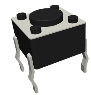 |
| 1 | Conector pentru alimentare | 9V, barrel | Power1 | 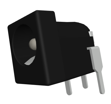 |
| 1 | Circuit integrat | 555 | U1 | 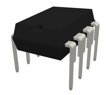 |
| 1 | Circuit integrat | CD4017 | U2 | 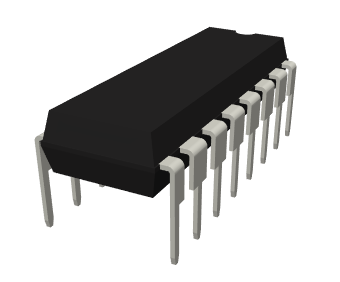 |
| 1 | Soclu | 8 pins | U1 | 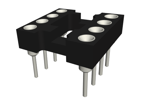 |
| 1 | Soclu | 16 pins | U2 | 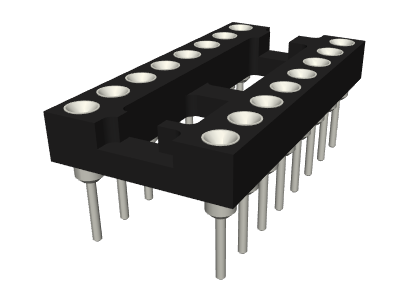 |
| 1 | PCB | 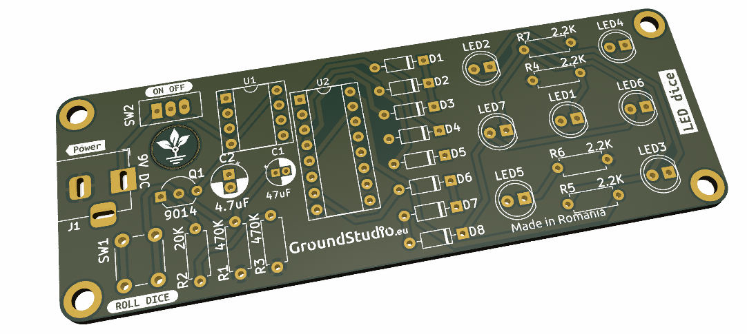 |
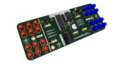
Schema electronică
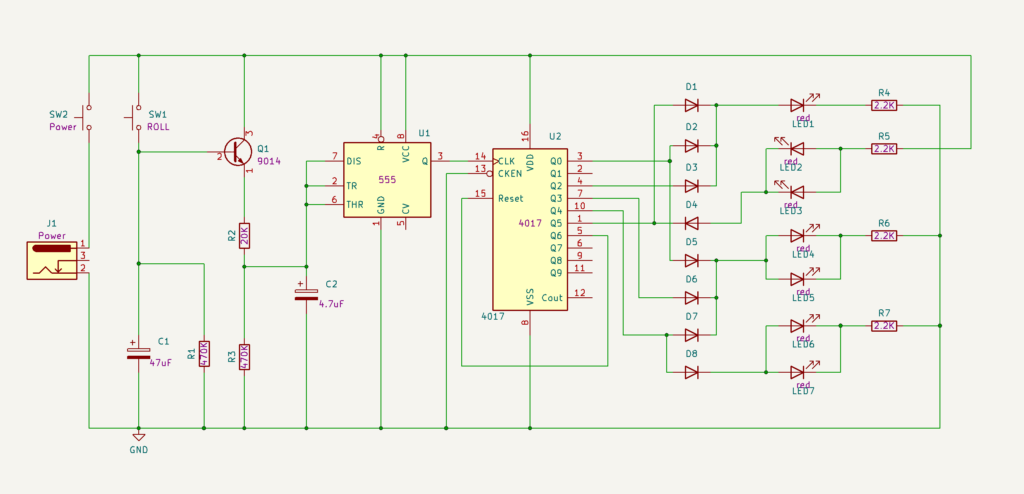
Principiul de funcționare
Acest circuit simuleaza aruncarea zarului. La simpla apasare a butonului, va porni un joc de lumini scurt si aleator pe cele 7 leduri. Apoi ledurile vor ramane aprinse sub forma unei fatete de zar, reprezentand un numar aleator intre 1 si 6.
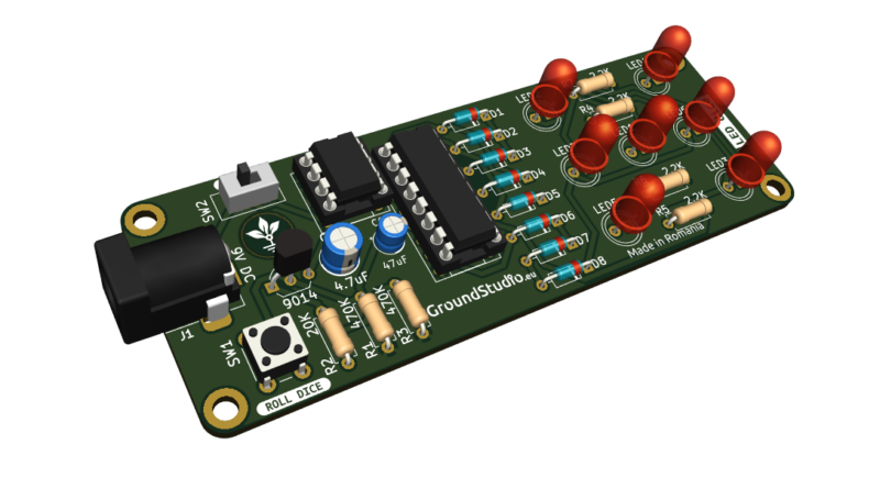
Acest circuit simulează aruncarea zarului. La simpla apăsare a butonului, va porni un joc de lumini scurt și aleator pe cele 7 leduri. Apoi ledurile vor rămâne aprinse sub forma unei fațete de zar, reprezentând un număr aleator între 1 și 6. Proiectul folosește timerul 555 ca oscilator, împreună cu componente R2, R3 și C2. La apăsarea butonului S1, condensatorul C1 se încarcă rapid la tensiunea de alimentare, iar circuitul începe să funcționeze. După ce butonul este ridicat, circuitul mai funcționează doar atât timp cât condensatorul C1 se descarcă. După descărcare, oscilatorul se oprește.
Din acest motiv, folosim și circuitul numărător 4017. Acesta îndeplinește funcția de contor până la 10 și numără impulsurile primite de la circuitul 555. În mod normal, valorile de la 0 la 9 sunt transpuse în ieșiri pe pini 1-9 ai circuitului. În cazul nostru, ieșirea a 7-a este conectată la reset, deoarece avem nevoie de numărare doar până la 6. Cu alte cuvinte, fiecare puls de la 555 va determina 4017 să activeze următoarea ieșire, iar la fiecare al 7-lea puls se va reseta poziția. Ledurile corespunzătoare fiecărei fețe a zarului sunt conectate pe cele 6 ieșiri.
Instrucțiuni pentru pregătirea asamblării
| Step | Detalii |
|---|---|
| 0. | Citește toate instrucțiunile, de la început și până la sfârșit. |
| 0 bis. | Reminder: E foarte important să citești toate instrucțiunile din acest document |
| 1. | Asigură-te că ai toate uneltele necesare asamblării kitului. |
| 2. | Asigură-te că ai toate componentele necesare asamblării kitului. |
| 3. | Pentru a respecta condițiile de garanție*, verifică/măsoară fiecare componentă în parte. |
Instrucțiuni de asamblare
| Step | Detalii | Imagine |
|---|---|---|
| 1. | Cositorește rezistorii conform marcajelor de pe PCB, indiferent de orientare. Ai grijă să respecți valorile și marcajele | |
| 2. | Cositorește diodele IN4148, astfel încât terminalul marcat de pe diodă (cel negativ adică) să corespundă celui de pe PCB | |
| 3. | Cositorește soclurile, astfel încât marcajele decupate să corespundă celor de pe PCB | |
| 4. | Cositorește ledurile, astfel încât terminalul mai lung (cel pozitiv adică) să corespundă semnului "+" de pe PCB | |
| 5. | Cositorește condensatorii electrolitici, astfel încât terminalul mai scurt (cel negativ, catodul) să corespundă zonei hașurate de pe PCB | |
| 6. | Cositorește tranzistorul conform marcajului de pe PCB | |
| 7. | Cositorește conectorul pentru alimentare conform marcajului de pe PCB | 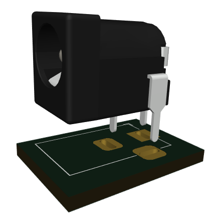 |
| 8. | Cositorește butonul SW1 conform marcajului de pe PCB, indiferent de orientare | 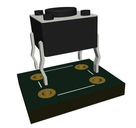 |
| 9. | Cositorește butonul SW2 conform marcajului de pe PCB, indiferent de orientare | 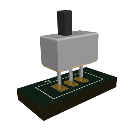 |
| 10. | Introdu circuitele integrate 555 si 4017 in soclul lor, astfel încât marcajele decupate să corespundă celor de pe PCB | |
| 11. | If you haven’t done it yet, cut all the terminals at the base of the solder joint with a wire cutter, so there is no risk of them touching each other and causing a short circuit. | 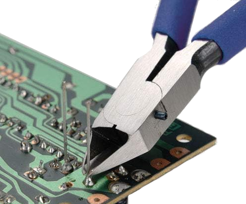 |
| 12. | Alimentează circuitul cu sursa aleasă | 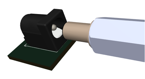 |
| 13. | Pune butonul slider pe pozitia ON | 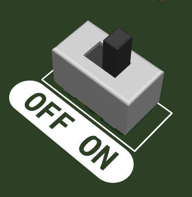 |
| 14. | Apasă butonul SW1 și bucură-te de zarul tău electronic! |  |
Instrucțiuni generale de asamblare în vederea respectării garanției
Ca o măsură de precauție și pentru respectarea condițiilor de garanție, recomandăm testarea fiecărei componente în parte înainte de momentul asamblării. De exemplu, rezistorilor li se va măsura valoarea cu un ohmmetru/multimetru. Kiturile sunt garantate pe fiecare componentă în parte, nu pe tot ansamblul. Deoarece asamblarea se face de către personal neautorizat, în condiții necunoscute sau în stadii necunoscute de finalizare, nu ne putem asuma nicio răspundere legală legată de orice urmări sau de funcționarea dispozitivelor asamblate de către orice terță parte.