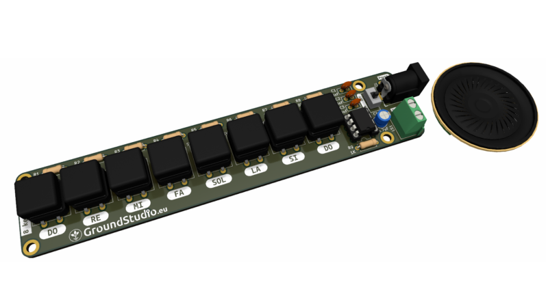
8-key Synth (piano)
Introduction
This circuit simulates a 8-key synthesizer, an electronic musical instrument that generates sounds (1 octave) based on different frequencies signals. It is designed for educational purposes, for introducing young learners to the world of sound synthesis. It can be powered by a 9V battery and used as a standalone device.
List of tools required for assembly and operation,
not included in the kit
| Name | Image | Buy here |
|---|---|---|
| Soldering iron |  | |
| Solder wire |  | |
| Pliers |  | |
| Helping hands (device or a friend) | 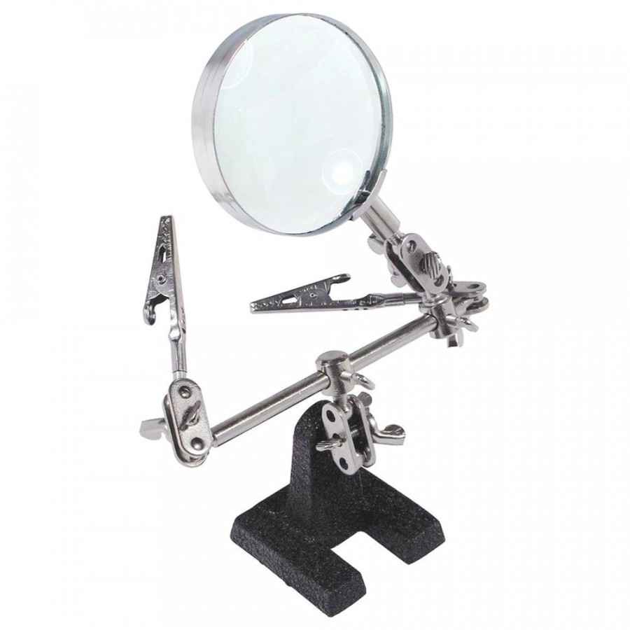 | |
| Phillips Screwdriver |  | |
| Wire stripper |  | |
| 9V power supply * |
*To power the circuit, you‘ll need a 9V power supply with a DC connector.
Here are some suggestions:
| Connector for 9V battery + battery | 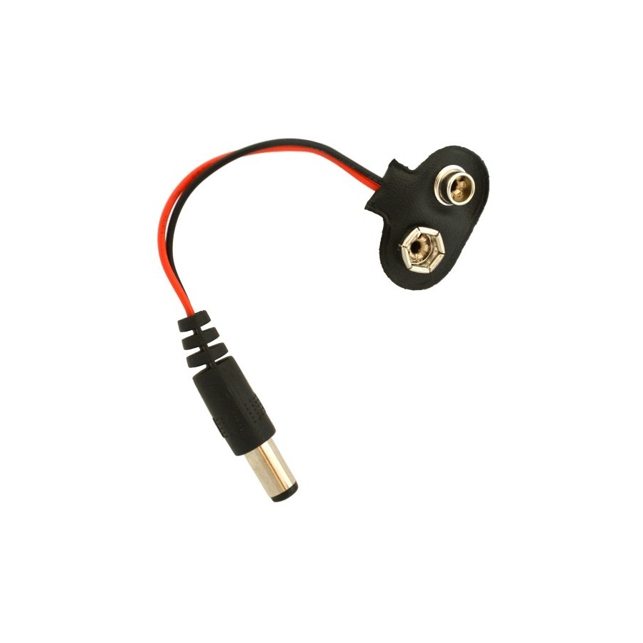 +  | |
| 9V power supply | 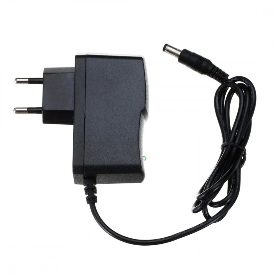 |
List of components included in the kit
| Qty | Name | Details | Footprint | Image |
|---|---|---|---|---|
| 8 | Push button | square key | SW1-SW4 | 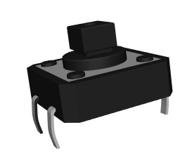 |
| 8 | Button cap | 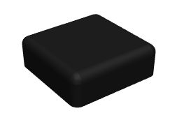 | ||
| 6 | Resistor | 2K | R1 – R6 | 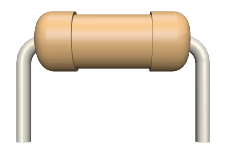 |
| 2 | Resistor | 1K | R7, R9 | |
| 1 | Resistor | 10K | R8 | |
| 1 | Electrolytic capacitor | 4.7uF | C4 | 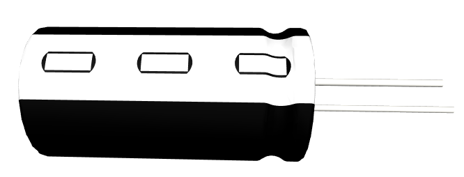 |
| 3 | Ceramic capacitor | 100nF | C1-C3 | 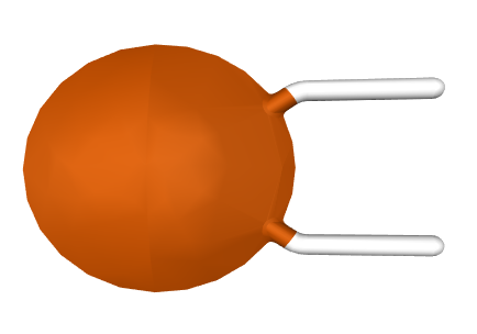 |
| 1 | Power connector | jack barrel, 9V | J1 | 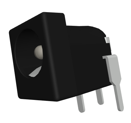 |
| 1 | Screw terminal connector | LS1 | 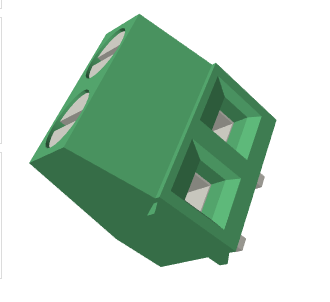 | |
| 1 | Speaker | 8ohm |  | |
| 1 | Cable for speaker | |||
| 1 | Integrated circuit | 555 | U1 | 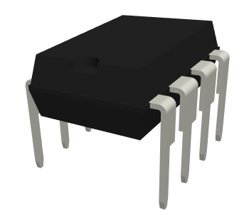 |
| 1 | Slider button | ON/OFF | SW9 | 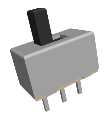 |
| 1 | Socket | 8 pin | U1 | 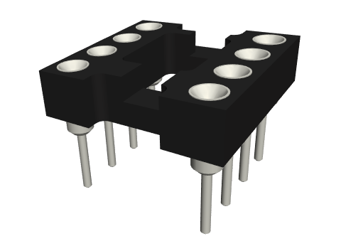 |
| 1 | PCB |
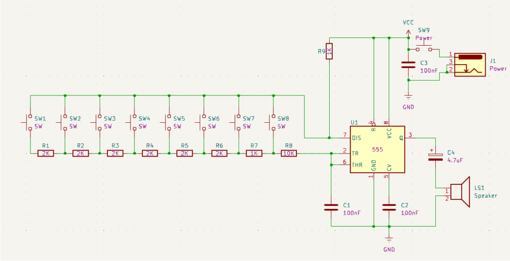
Schematic
Working principle
In this project, the speaker generates sounds based on the frequency of the received signal. The higher the frequency, the higher-pitched the generated sound. This allows us to produce musical notes by simply adjusting the signal frequency at the speaker terminals.
Therefore, we need a variable pulse generator. The 555 integrated circuit can perform this function easily. The pulse frequency depends on the value of capacitor C1, resistor R9, and the equivalent resistance resulting from pressing a button.
For example, when we press the SW1 button, the equivalent resistance between pins 7 and 2 of the 555 integrated circuit will be the sum of all resistors from R1 to R8. A high resistance, according to the calculation formula of the 555, will generate a low frequency on the Q output, thus a low note in the speaker. Similarly, if we press the last button, SW8, the equivalent resistance will only be formed by R8, so the generated signal will have a higher frequency, and the sound will be higher-pitched.
Instructions for assembly preparation
| Step 0 | Read all the instructions, from beginning to end. |
| Step 0 bis | Reminder: It is very important to read all the instructions. |
| Step 1 | Make sure you have all the tools needed to assemble the kit. |
| Step 2 | Make sure you have all the components needed to assemble the kit. |
| Step 3 | To comply with the warranty conditions*, check/measure each component separately. |
Assembly instructions
| Step | Details | Image |
|---|---|---|
| Step 1 | Solder the resistors according to the markings on the PCB, regardless of orientation. Make sure you respect the values and markings | |
| Step 2 | Solder the electrolytic capacitors, so that the shorter terminal (the negative one, the cathode) corresponds to the hatched area on the PCB | |
| Step 3 | Solder the ceramic capacitors, regardless of orientation | |
| Step 4 | Solder the SW1-SW8 push buttons according to the marking on the PCB, regardless of orientation | 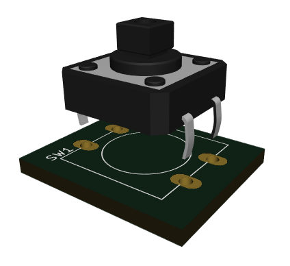 |
| Step 5 | Solder the SW9 slider button according to the marking on the PCB, regardless of orientation | 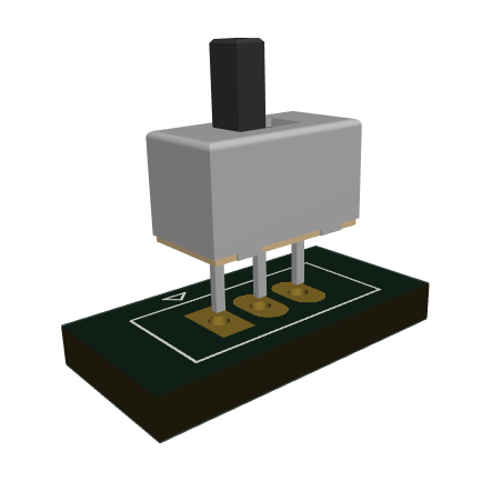 |
| Step 6 | Solder the screw terminal connector with the holes oriented towards the edge of the PCB. | 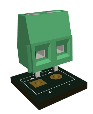 |
| Step 7 | Solder the socket so that the cut-out markings correspond to those on the PCB | |
| Step 8 | Solder the power connector according to the marking on the PCB | 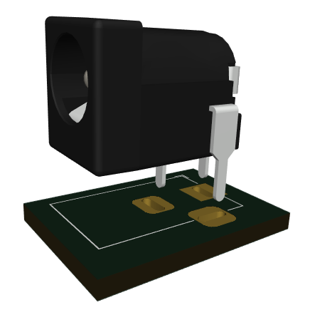 |
| Step 9 | Insert the 555 integrated circuit in its socket, so that the cut-out marking correspond to the one on the PCB | |
| Step 10 | Mount the caps on the buttons | 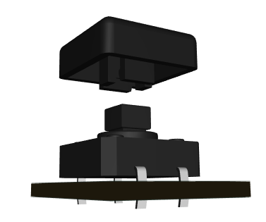 |
| Step 11 | Strip the wires on both ends | 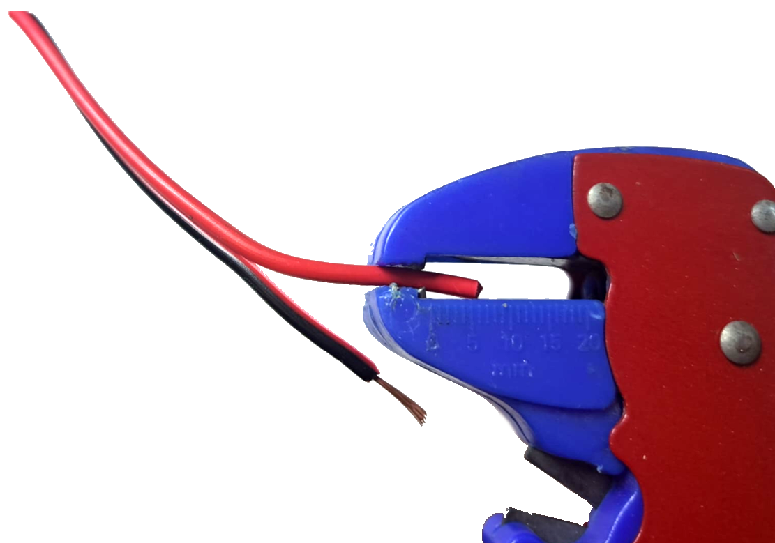 |
| Step 12 | Solder the wire ends on the speaker | 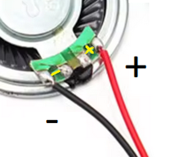 |
| Step 13 | Insert and screw the other ends of the wire to the screw terminal connector, but pay attention to the speaker’s and connector’s polarity (+ to +, – to -) | 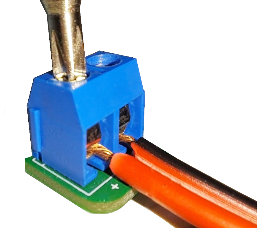 |
| Step 14 | Power the circuit with the chosen power supply | 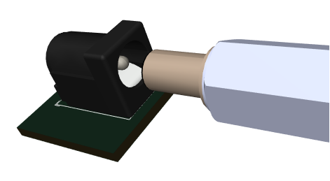 |
| Step 15 | Put the slider button on the ON position | 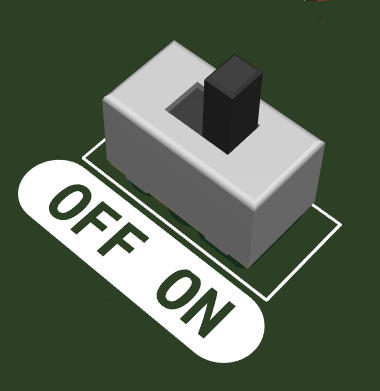 |
| Step 16 | Enjoy your electronic keyboard! |  |
General assembly instructions for Warranty Compliance
As a precaution and to comply with the warranty conditions, we recommend testing each individual component before assembly. For example, resistors will be measured with an ohmmeter/multimeter. The warranty is for each individual component, not for the whole assembly. Since assembly is done by unauthorized personnel, under unknown conditions or at unknown stages of completion, we cannot assume any legal liability related to any consequences or operation of devices assembled by any third party.