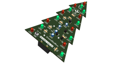
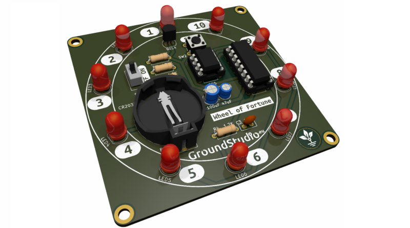
Roata norocului
Introducere
Acest circuit simulează rotirea unei roți a norocului. Cu o simplă apăsare a butonului, va începe un spectacol de lumină pe cele 10 LED-uri. Curând după aceea, mișcarea luminii se va opri, și va rămâne aprins doar un LED, reprezentând poziția roții, un număr aleatoriu între 1 și 10.
Uneltele necesare asamblării și funcționării, neincluse in kit
| Nume | Imagine | Buy Here |
|---|---|---|
| Letcon | 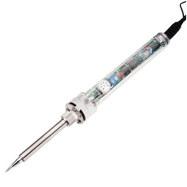 | |
| Fludor | 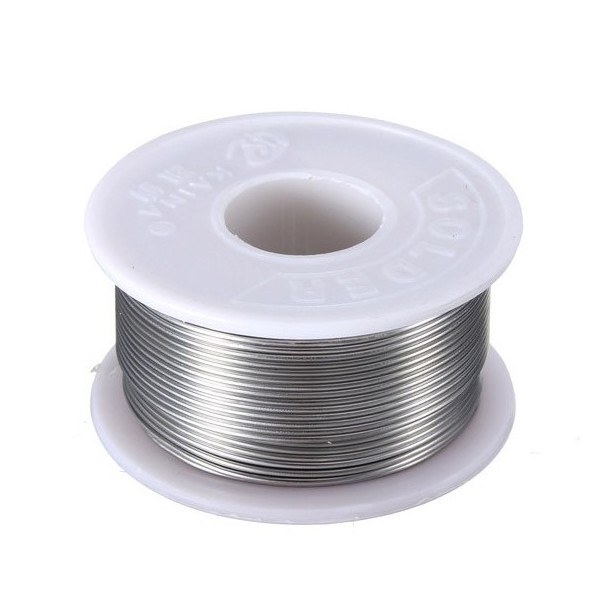 | |
| Clește pentru fire |  | |
| Helping hands (dispozitivul sau un prieten) | 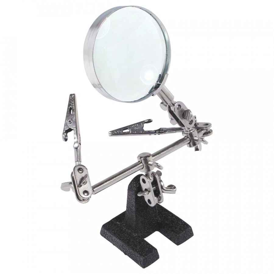 | |
| Baterie CR2032 | 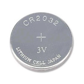 |
Componentele incluse în kit
| Cantitate | Nume | Detalii | Footprint | Imagine |
| 2 | Rezistor | 1.2K, 1/4W | R2, R4 | 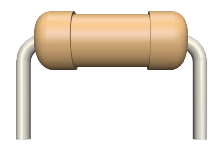 |
| 2 | Rezistor | 470K, 1/4W | R1, R3 | |
| 10 | LED | 5mm, roșu | LED1, LED2, LED3, LED4, LED5, LED6, LED7, LED8, LED9, LED10 | 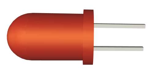 |
| 1 | Tranzistor | S9014 | Q1 | |
| 1 | Condensator electrolitic | 100uF | C1 | 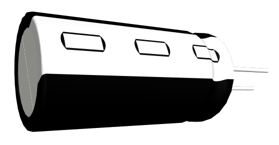 |
| 1 | Condensator electrolitic | 47uF | C2 | |
| 1 | Condensator ceramic | 103 | C3 | 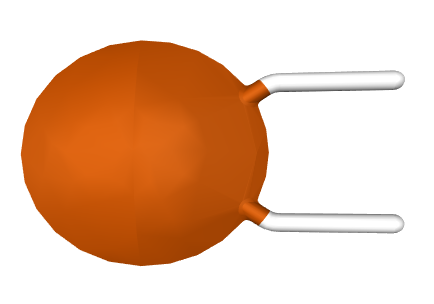 |
| 1 | Suport de baterie | CR2032 | BT1 | 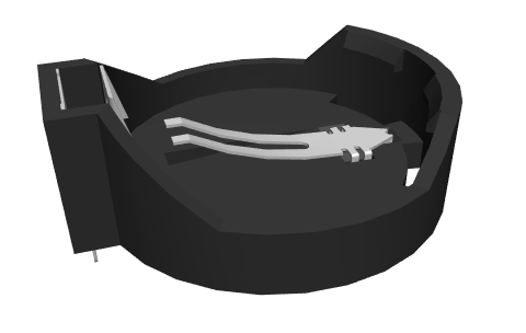 |
| 1 | Circuit integrat | 555 | U1 | 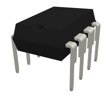 |
| 1 | Circuit integrat | CD4017 | U2 | 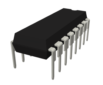 |
| 1 | Soclu | 8 pins | U1 | 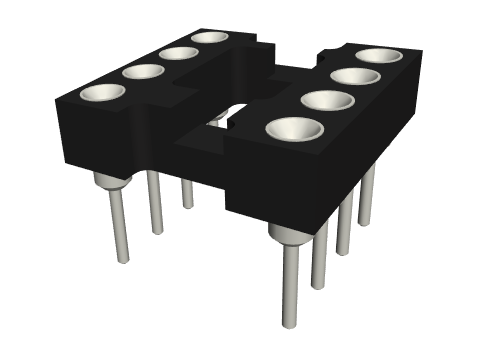 |
| 1 | Soclu | 16 pins | U2 | 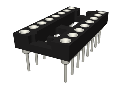 |
| 1 | Buton slider | ON OFF | SW1 | 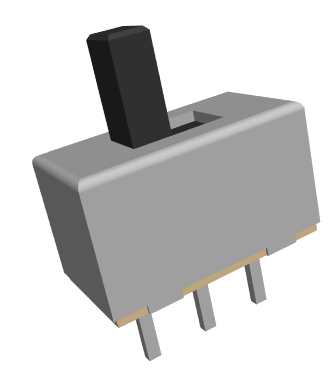 |
| 1 | Buton | SPIN | SW2 | 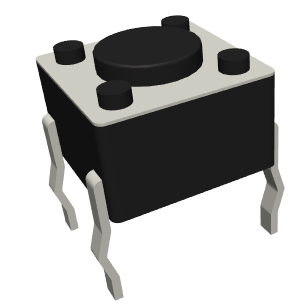 |
| 1 | PCB | 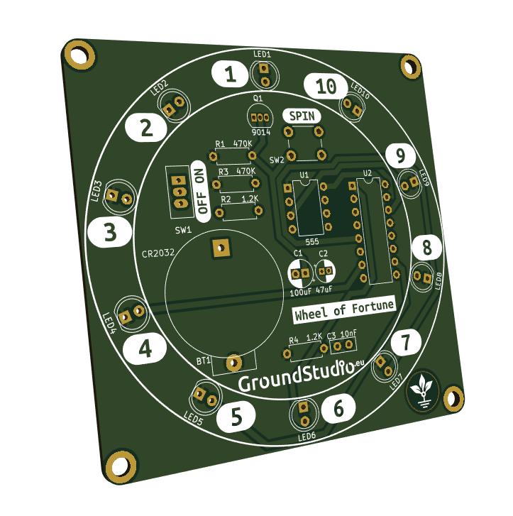 |
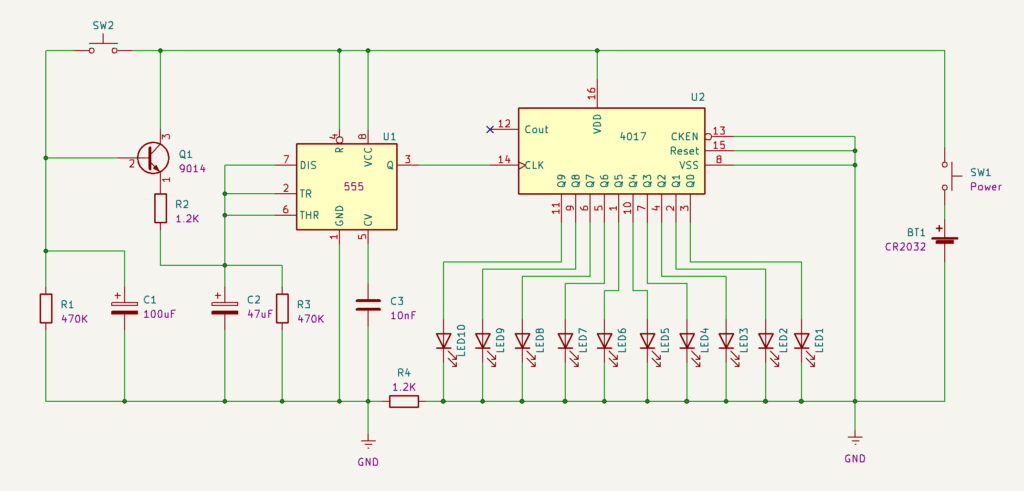
Schema electronică
Principiul de funcționare
Acest circuit simulează rotirea unei roți a norocului. Cu o simplă apăsare a butonului, va începe un spectacol de lumină pe cele 10 LED-uri. Curând după aceea, mișcarea luminii se va opri, și va rămâne aprins doar un LED, reprezentând poziția roții, un număr aleatoriu între 1 și 10.
Proiectul folosește un timer 555 ca oscilator, împreună cu componente R2, R3 și C2. Când butonul SW2 este apăsat, condensatorul C1 se încarcă rapid la tensiunea de alimentare, și circuitul începe să funcționeze. După ce butonul este eliberat, circuitul continuă să funcționeze doar atât timp cât condensatorul C1 se descarcă. Odată descărcat, oscilatorul se oprește.
Folosim și circuitul contor CD4017. Acesta servește ca un contor până la 10, numărând impulsurile primite de la circuitul 555. Fiecare impuls va face ca CD4017 să activeze ieșirea următoare, și la fiecare al 11-lea impuls va reseta poziția. Valorile de la 1 la 10 sunt traduse în ieșirile Q0-Q9 ale circuitului. Astfel, LED-urile în acest proiect se vor aprinde unul câte unul, până când 555 încetează să trimită impulsuri.
Instrucțiuni pentru pregătirea asamblării
| Step | Detalii |
|---|---|
| 0. | Citește toate instrucțiunile, de la început și până la sfârșit. |
| 0 bis. | Reminder: E foarte important să citești toate instrucțiunile din acest document |
| 1. | Asigură-te că ai toate uneltele necesare asamblării kitului. |
| 2. | Asigură-te că ai toate componentele necesare asamblării kitului. |
| 3. | Pentru a respecta condițiile de garanție*, verifică/măsoară fiecare componentă în parte. |
Instrucțiuni de asamblare
| 1. | Cositorește rezistorii conform marcajelor de pe PCB, indiferent de orientare. Ai grijă să respecți valorile și marcajele | |
| 2. | Cositorește soclurile, astfel încât marcajele decupate să corespundă celor de pe PCB | |
| 3. | Cositorește ledurile, astfel încât terminalul mai scurt (cel negativ, catodul) să corespundă semnului "-" de pe PCB | |
| 4. | Cositorește condensatorii electrolitici, astfel încât terminalul mai scurt (cel negativ, catodul) să corespundă zonei hașurate de pe PCB | |
| 5. | Cositorește condesatorii ceramici, indiferent de orientare | |
| 6. | Cositorește tranzistorul conform marcajului de pe PCB | |
| 7. | Cositorește butonul SW2 conform marcajului de pe PCB, indiferent de orientare | 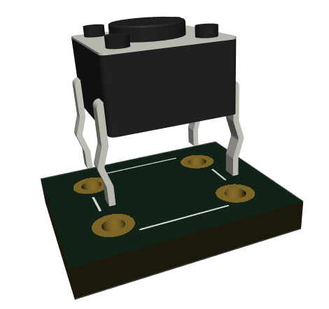 |
| 8. | Cositorește butonul slider SW1 conform marcajului de pe PCB, indiferent de orientare | 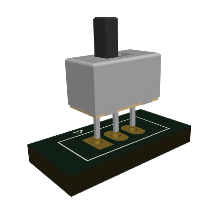 |
| 9. | Introdu circuitele integrate 555 si 4017 in soclul lor, astfel încât marcajele decupate să corespundă celor de pe PCB | |
| 10. | Cositorește suportul de baterie | |
| 11. | Dacă nu ai făcut-o încă, taie toate terminalele la baza lipiturii cu un clește, astfel încât să nu existe riscul de a se atinge între ele și de a provoca un scurtcircuit. | 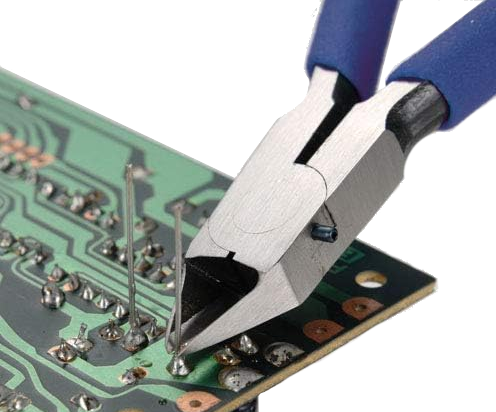 |
| 12. | Introdu bateria in suport | |
| 13. | Pune butonul slider pe pozitia ON | 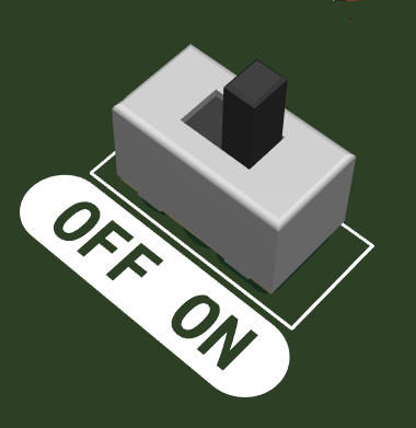 |
| 14. | Apasă butonul SW2 și bucură-te de roata norocului electronică. |  |
Instrucțiuni generale de asamblare în vederea respectării garanției
Ca o măsură de precauție și pentru respectarea condițiilor de garanție, recomandăm testarea fiecărei componente în parte înainte de momentul asamblării. De exemplu, rezistorilor li se va măsura valoarea cu un ohmmetru/multimetru. Kiturile sunt garantate pe fiecare componentă în parte, nu pe tot ansamblul. Deoarece asamblarea se face de către personal neautorizat, în condiții necunoscute sau în stadii necunoscute de finalizare, nu ne putem asuma nicio răspundere legală legată de orice urmări sau de funcționarea dispozitivelor asamblate de către orice terță parte.